
Wireless trends and placement of 4G antennas in smaller spaces
The growth in the ‘Internet of Things’ (IoT), wireless appliances, and wearable electronics have created strong wireless trends towards smaller, more compact electronic devices. For those working on new electronic designs with wireless connectivity, the reduction in size creates some interesting challenges. Geoff Schulteis, Senior Antenna Applications Engineer, Antenova, explains.
Shrinking a design initially may not appear to be difficult, but chip antennas need a certain amount of three-dimensional area to perform correctly, it is the physics of how antennas operate that poses a challenge. This article looks at the trends and challenges of how designers are fitting antennas into smaller applications.
The IoT market is very different and far wider than the machine-to-machine telematics market of 5-10 years ago. With tiny antennas readily available, almost any small device can be re-invented as a wireless device, with tracking and monitoring applications being some of the most popular.

Above: Figure 1. shows the relationship between antenna ground plane length and antenna performance for a tracking antenna SR4G008, (results were measured in Antenova’s anechoic chamber)
There are thousands of uses for antennas within vehicles. These might be in navigation, tracking, fleet management, in-car entertainment or electronic controls with sensors within the engine compartment.
The health sector is increasingly using devices to monitor patients remotely and track equipment, and can even utilise sensors to detect if hospital beds are occupied or not.
We are also seeing large roll-outs of smart city applications that control lighting, building environments, traffic, and energy meters.
Above: Figure 1. shows the relationship between antenna ground plane length and antenna performance for a tracking antenna SR4G008, (results were measured in Antenova’s anechoic chamber)
There are plenty of networks out there: GSM, GPRS, CDMA, 4G LTE, GPS, GNSS, Wi-Fi, Bluetooth, ISM, LoRa, and NB-IoT, and soon 5G as well, and the applications may be single frequency with one antenna or multi-band with multiple antenna, utilising more than one network.
What the new applications all have in common is their size. There is a strong trend towards smaller devices and smaller PCBs. This comes at the same time as a gradual shift to 4G, with 5G now appearing large on the horizon. This is where we find the first challenge to the designer.
Shrinking ground planes
Ground planes are becoming smaller. A chip antenna, or embedded antenna, typically works by using the surface of the PCB it is mounted to as a radiator, which we call the counterpoise of the antenna or in other terms, its ground plane. An antenna can only resonate at whole number multiples or fractions of its wavelength, with the shortest resonant length being one quarter of the wavelength of the antenna at its lowest frequency.
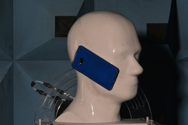
Above: Figure 3. shows test equipment in an anechoic chamber
This property of a radiating element dictates the length of the ground plane, which needs a space on the PCB. For example, a full-wave antenna operating at 916MHz would require a ground plane 327mm long to perform efficiently. This is too large to be practical, so a quarter wave version would usually be used, which would require a ground plane length of 87.2mm.
This relationship between frequency, efficiency and ground plane size means that for a chip antenna to perform well at lower frequencies, the design becomes more sensitive when the ground plane is less than 100mm in length.
Global 4G coverage
As the move from 2G and 3G to 4G continues, the separation between bands used in the US and those used in Europe is not as distinct as it was in years past. Europe traditionally used the frequencies between 791MHz and 2,690MHz while the US used 698MHz to 2,690MHz, but now most people want devices that will operate on the 4G networks anywhere in the world, so manufacturers prefer to offer one solution that can be used globally – an antenna solution that covers all these frequencies, and provides fallback to 2G.
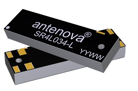
4G antennas for short ground planes
An example of an antenna for new 3G and 4G devices is the SR4L034 that measures 28.0mmx8.0mmx3.3mm, covers the full range of frequencies from LTE, GSM, CDMA, DCS, PCS, WCDMA, UMTS, HSPDA, GPRS, EDGE, IMT, 698-960MHz; 1710-2170MHz; 2300-2400MHz; and 2500-2690MHz. It uses a ground plane, but in this case the ground plane is not below the antenna itself. The SR4L034 can be used either as a single antenna or in a pair such as in a MIMO system. This antenna was specifically designed for coexistence with other antennas using minimal space requirements and is typically placed on the corner of the PCB to save space.
Wearable devices and trackers
Some of the smallest devices will be wearables, such as internet watches, fitness devices and small tracking devices used to trace pets and livestock. Action cameras also require small form factors with wireless versatility for remote device connectivity and image tracking. Chest worn police, fire and medical cameras are quickly becoming necessary for job safety.
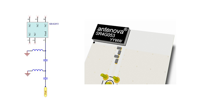
Above: Figure 4. shows the matching circuit for an antenna with a small ground plane
Wearables are not just some of the smallest devices, they also bring the additional challenge of needing to operate close to the human body, which tends to absorb and block antenna signals. The antenna needs clearance to radiate in six directions so that they can operate most effectively.
Designs for wearables and similar devices are best tested inside an anechoic chamber with a phantom head, torso or arm and wrist, to understand how the device will behave next to the body.
Low profile antennas for small trackers
One way to include an antenna in a reduced space is to choose an antenna with less volume. The SR4G008 is an ultra-thin compact antenna measuring 7.0mm x 5.8mm x 0.4mm. It can be used for positioning applications where it matches the performance of a ceramic patch antenna despite its ultra-low profile and does not require a direct view of the sky. Operating at 1,559–1,609MHz, it would be chosen for applications using global public satellite constellations like GPS, GLONASS, Beidou and GALILEO. This antenna works best on a minimum recommended host PCB size of 40 x 20mm or larger.
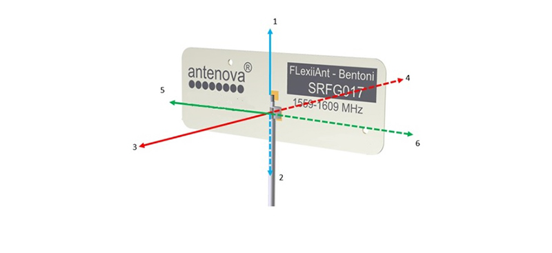
Above: Figure 5. shows the six spatial directions relative to FPC antenna
A newer solution, SR4G053 measures 16.0mm x 8.0mm x 1.7mm and offers a location finding accuracy to within 10cm. This chip antenna has right hand circular polarisation (RHCP) characteristics suitable for GNSS signals and matches the performance of an 18mm x 18mm x 4mm ceramic patch antenna.
Use of a matching circuit
A matching circuit can tune an antenna to boost its efficiency in a small space by ensuring the desired frequencies resonate in their proper bands. This needs to be optimised for each design. The matching circuit can require up to four components and should be designed into the PCB layout so the correct circuit can be installed. The matching network should be placed close to the antenna feed to ensure it is more effective in tuning the antenna.
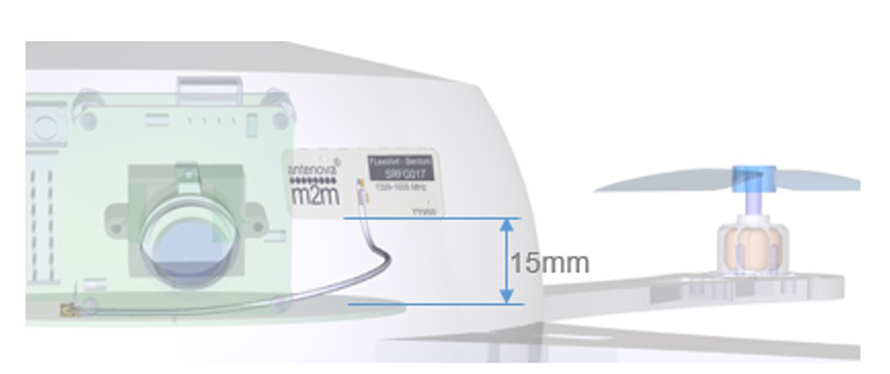
Above: Figure 6. shows the antenna placed inside the casing of a drone, away from other components, in this example with ample clearance at 15mm
Flexible antennas
Flexible antennas are easier to integrate in a small space, as they do not require a ground plane, and the flat portion of the antenna can be folded to insert it into a small space.
The illustration shows SRFG017, a positioning antenna with a cable enabling direct connection to the host PCB for easy integration.
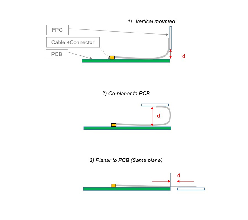
With flexible antennas, the host PCB size is not a limiting factor as it is with PCB mounted antennas, but the placement of the antenna still needs to follow some basic rules, as any antenna is sensitive to its environment.
Above: Figure 7. shows the recommended antenna placement inside the housing of a device, away from other components, with ample clearance in 5 spatial planes
The diagram left shows how an antenna radiates in six spatial directions. Most of these need to be free of obstruction if the antenna is to achieve its best performance, and a minimum of three directions should be free from obstructions to allow the antenna to operate effectively. The other directions may have some obstruction in their path, but these directions still require a minimum clearance.
The advantage of the FPC is that it can be bent, and takes very little space. The example below shows a similar flexible antenna integrated into a drone. The major components are shown along with the outer case of the device and the antenna. The FPC is shown adhered to the inside of the device’s plastic housing. The length of the cable should be chosen to be sufficiently long enough to allow ease of assembly during the manufacturing process.
Product Spotlight
APV1111GVY
Panasonic

Panasonic PhotoMOS® Photovoltaic MOSFET High-Power Drivers
| SKU: | |
|---|---|
| Stock: | 3490 |
| Cost: | $3.95 |
