
Top tips on how to build a robotic hand
Ben Lopez checked out some of the Jameco's submitted projects when he found the Robotic Hand Kit by designer Anshul Sanam. He thought it was a great kit for getting started with motors, sensors or even animatronics. Lopez wanted to take on the challenge of making a hand. Here, he gives his top tips on how to build a robotic hand.
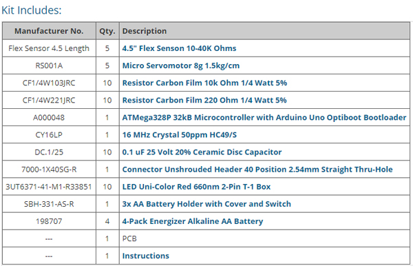
With a few exceptions, everything you need is provided in the kit. You can find the rest of your items around the house or at your local hardware store.
 Part 1: Assembling the hand
There's a lot of information about the electronics included in this kit, however, there isn't a guide on assembling the hand itself. I decided to build a robotic hand similar to the one I found on the Instructables website.
I cut long 'fingers' out of wiring tube and was able to fasten one end to a CD by splicing the ends and super gluing them together.
After the glue had dried, I cut holes at the bending points of the fingers to make knuckles. Next, I poked a hole through the free end of each finger and threaded the nylon string through the holes and down the fingers. Leaving enough string to attach to the motors, I then strung the nylon string through the plastic arms and attached them to the motors. The holes in the arms were a bit small, so I drilled them out a bit larger.
For the next step, I had to mount the 'hand' and the motors to the same piece of material - this is where I had to get creative. I decided to use Styrofoam because it was easy to cut with an Exacto blade and easy to work with (but don't try to use super glue with it!). I cut five rectangular holes in the Styrofoam block the same size as the motors. To run the motor wires out, I also cut small holes into the side of the rectangular holes.
I assembled the CD hand and servo motors into the block of Styrofoam - and this is where I learned something about superglue the hard way. I used superglue to hold the hand and motors in place, and immediately regretted it as I stood and watched it dissolve the Styrofoam. I had to let it set overnight before I could continue, so please, do yourself a favour and don't use superglue.
I ended up using duct tape to fasten the hand to the block as shown here below. Just pop the plastic arms onto the servos and this project is ready for circuitry.
Part 2: Assembling the circuit
The designer's instructions were pretty straightforward on how to assemble the circuitry for the project, and the microcontroller comes pre-programmed and ready to solder to the printed circuit board. You can follow the instructions but keep in mind that your components (capacitors) may look a bit different than the designer's components. Be sure to keep track of capacitor labels.
All in all there were only a few components to solder to the small PCB. Most soldering is done on the microcontroller pins.
I ran into a few ambiguities while assembling the circuit using the designer's step-by-step instructions.
Here are a few tips I picked up along the way:
- I recommend soldering a socket to the PCB instead of the ATmega chip itself, so you can easily re-programme it or replace it later. (Step 5)
- Use the 220Ω resistors provided where the designer specifies 330Ω resistors. I used the 220Ω resistors and the project works great. (Step 8)
- In case your LED does not have a flat side, the negative LED terminal is the short leg. (Step 10/11)
- The positive/negative power terminals on the PCB were not specified, so I tested for continuity between the positive power terminal and a positive motor terminal. The power terminal on the outer side of the board is the positive terminal and the inner terminal is negative (Step 17).
Part 3: Assembling the glove/flex sensors
The flex sensors included in the kit are nice because they sense a resistance value, which means that the terminals do not have to correspond to specific positive/negative terminals. The black and white leads are not in the same order for every finger. This doesn't matter as long as the flex sensor wires from the fingers on the glove correspond to the terminals within the correct square on the board.
Have some fun and get creative with the glove portion of this project! I took the designer's approach and taped the sensors to a glove. With this method, the tape tends to come off over time since you're constantly stretching the glove, so you might want to consider putting an elastic glove on over the sensors instead.
Your new hand is wired and ready to go! Just turn it on and calibrate the sensors within the first few seconds by opening and closing your hand quickly. I thought the code for this kit was well written and it works great.
What else can you do with it?
This is a good starting point for many other electronic DIY projects. Can you make the hand sign words or letters that it hears through a microphone? How about make one with muscle wire for actuators instead of motors? Could you make an entire arm?
Product Spotlight
APV1111GVY
Panasonic

Panasonic PhotoMOS® Photovoltaic MOSFET High-Power Drivers
| SKU: | |
|---|---|
| Stock: | 3490 |
| Cost: | $3.95 |
