
Efficient and accurate drives for robotic applications
The robotics market has seen a significant growth in business over the past decade, and their presence has become more common. Frank Malik, Principal Engineer Solution Marketing, Toshiba Electronics Europe, discusses the technology that is driving them forward.
To those growing up during the late 20th century, robots still had a science-fiction flair. After all, they were still a rarity, with a large proportion of them being hidden away in automotive manufacturing, welding together car chassis. These motorised machines provided a significant boost to productivity and manufacturing accuracy but were coupled with a significant level of investment to reap those benefits. Since then, much has changed with significant advancements in motor control technology, simulation environments, and connectivity.
While industrial robots still account for the greatest proportion of units sold, the areas of collaborative robotics and mobile robotics (such as Autonomous Guided Vehicles, AGV) are growing rapidly. In addition, human-robot hybrid technology, such as exoskeletons that help humans manipulate heavy loads, are another exciting area of development. Coupled with the uptake in connectivity thanks to Industry 4.0 initiatives, and the drop-in cost for artificial intelligence (AI) vision systems for the detection of objects and work pieces, the technology choices for manufacturers is broadening while investment costs are dropping. As a result, lighter and highly adaptable robotic systems look commercially attractive even for relatively complex but, for humans, mundane manual tasks.
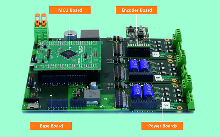
Above: Figure 1. The Servo Drive RM is highly modular, allowing a broad range of servo motor approaches to be trialled and implemented
The robotics trilogy
Robotic systems require a trilogy of elements to control the motors used to implement the servo drives of each joint: a controller, an output stage and a feedback loop. In the past, the robotic arm’s motors and its control system would typically be two separate parts that were connected together on-site during installation. To remain compact and reduce the challenges of electromagnetic compatibility (EMC), many of today’s solutions integrate them together into the body of the robot arm itself. To ensure speed, accuracy, low weight and minimal heat dissipation, these control systems need to be compact and light, as well as highly efficient.
With brushless DC motors (BLDC) or stepper motors in use, a suitable microcontroller (MCU) needs to be selected for the control element. Today’s MCUs are not only exceptionally powerful with plenty of memory, they integrate complex peripherals that offload varying levels of the control complexity from the MCU’s processor. This is essential as motor control algorithms, such as field-oriented control (FOC) that minimise vibration for smooth control, are complex and processor intensive.
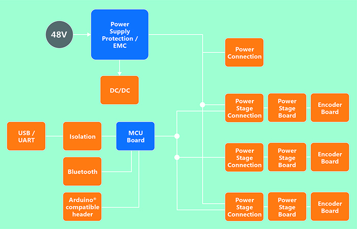
Above: Figure 2. The block diagram for the Servo Drive RM baseboard
The output stage, or motor inverter, needs to be constructed of power devices that offer low on-resistance to minimise power losses. The packaging of these device typically include a metal slug to help with heat dissipation. Thanks to the latest advances in packaging technology, solutions are available that are exceptionally compact and low in weight. This helps to keep the volume of the final solution to minimum, especially in slimline collaborative robot arms, Selective Compliance Articulated Robot Arms (SCARA) and delta robot designs.
The feedback loop, the third element of the trilogy, is typically implemented in the software of the control, determining the current position of the axes of the robotic solution from a range of sensors, such as Hall sensors, resolvers, or encoders. MCUs developed for motor control applications, such as those offered by Toshiba, offer input peripherals that not only automatically decode these inputs, they can also generate interrupt signals that can trigger actions in the software, rather than the software having to regularly poll their status.
Flexibility at every point
In order to develop an optimal solution for robotic servos, developers require the flexibility to quickly and easily swap out and test each of these three elements. This allows controller, power solution, and encoder to be assessed rapidly to achieve an optimal approach. Recognising the growing interest in this space, especially amongst startups targeting niche applications, Toshiba has developed the highly configurable Servo Drive Reference Model (RM) that draws all the required pieces together into a single platform (Figure 1).
It consists of a baseboard that provides the necessary connectivity between the three functional elements. Interchangeable microcontroller (MCU) boards sit atop this board, providing the motor control based upon the input from the encoder or resolver and in response to the input from an external motion controller. Up to three power boards can be attached to the side, controlling power to the motor coils, while a selection of encoder boards prepare the signals from encoders or resolvers for use by the MCU.
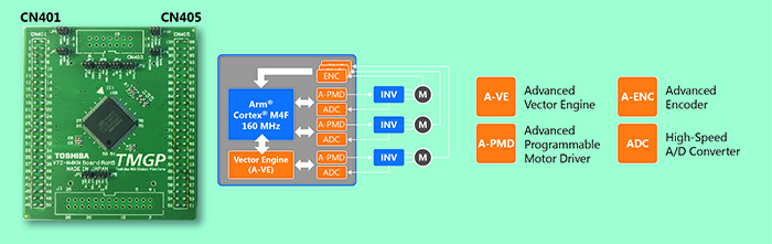
Above: Figure 3. A 100-pin variant of the microcontroller board featuring the M4K MCU that allows up to three motors to be FOC controlled; one with the hardware A-VE+ and two through a software FOC algorithm
In addition to the MCU plug-in area, the baseboard also provides a connector for Arduino-compatible shields. This allows the integration of CAN, Ethernet, or other networking protocols. For ease of system analysis, a USB-to-UART converter, isolated from the MCU, is also provided while debugging is supported through an easily accessible JTAG connector. Power, polarity protection, and level shifters, where needed, round off the design (Figure 2).
Dedicated controllers for accurate control
The MCU board is the home of the Arm Cortex M4F device from the M4K group. Operating at up to 160MHz, and with 256kB of flash and 24kB of SRAM, its floating-point unit is ideal for the execution of complex motor control algorithms. In addition, the MCU features a range of tightly coupled peripherals that optimally support motor control: an Advanced Vector Engine Plus (AV-E+) module, a 12-bit analogue-to-digital converter (ADC), and the Advanced Programmable Motor Control (A-PMD) timer block. By using the A-VE+ for Field Oriented Control (FOC) for one motor, the MK4 can support two further motors by executing FOC algorithms in software (Figure 3).
The A-VE+ block simplifies motor control implementations by adding much-needed determinism to the software, hiding the computational complexity of the Clark-Park transforms used. Positional information from an encoder or resolver, collected by the ADC, is converted from a 3-phase to 2-phase representation in hardware, processed, and then converted back into 3-phase for the A-PMD timer block. This hardware approach avoids the jitter caused by interrupts or operating system task switches, and compiler optimisations have minimal impact on algorithm execution time. Due to the tight integration between the three hardware peripherals, FOC motor control is almost autonomous once the system is configured.
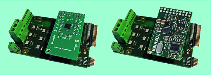
Above: Figure 4. The Differential Encoder (left) and Resolver Encoder (right) fit to the Power Boards and simplify the integration of such sensors with the Servo Drive RM platform
Resolvers and encoders are easily attached using the Differential Encoder and Resolver Encoder boards offered that connect to the low-power stage (Figure 4). More complex sensors, such as those with a Hiperface interface, can be supported in the same way. Incremental encoders are supported by the Advanced Encoder Input Circuit (A-ENC32) module. Its integrated noise canceller is an essential feature for the noisy electrical environment robots and AGVs face.
Efficient power delivery
The Low-Voltage Power Board provides the power stage for the motor selected. This accepts an input voltage of up to 48V and integrates a 3-phase inverter based upon TPW3R70APL 100V MOSFETs (Figure 5). It can handle power dissipation of up to 10W and a heatsink can be fitted if required. The MOSFET is based upon the U-MOS IX-H generation of process technologies that offer an improved trade-off between low on-resistance and Qg, QSW and QOSS. The device is part of a wider range of devices supporting voltages from 20V to 250V in both SMD and THD packages, some of which, such as DSOP, provide top-side cooling pads.
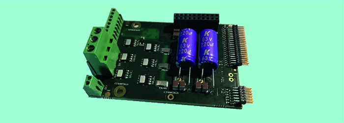
Above: Figure 5. The Low-Voltage Power Board featuring the latest generation U-MOSIX-H TPW3R70APL MOSFETs supporting motors of up to 200W
This makes the board suitable for BLDC motors in the 20W to 200W class. Current measurement is implemented in the low side, with a TC75W58FU comparator selected to provide a fault feedback signal to the baseboard. Further protection is implemented thanks to a temperature sensor. The phase currents for the motor are also linked back to the baseboard for use by the microcontroller.
The package is rounded off with demonstration software based upon a real-time operating system (RTOS) and well-documented software APIs. A graphical user interface (GUI) helps during development by highlighting, in real-time, firmware status and parameters for each axis of the robot implementation (Figure 6).
Summary
Thanks to the development of highly integrated MCUs matched to the needs of motor control, and the continuing advancements in power devices and packaging technology, robotic control systems are becoming more efficient, more accurate, and falling in cost. This is supporting the growing interest in collaborative robotic systems that can handle complex tasks that are, for humans, mundane and tiring.
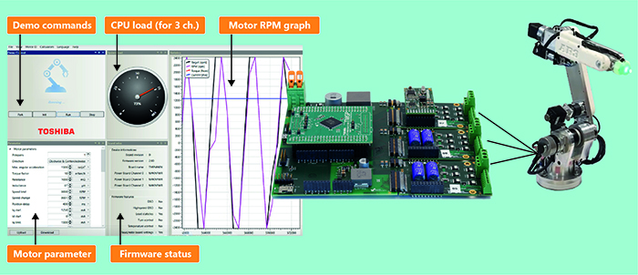
Above: Figure 6. An AR3 robot arm has been converted to use BLDC motors with Hall sensor encoders. This provides a demonstration platform for the Servo Drive RM GUI and firmware API
Furthermore, it is enabling AGVs that can seamlessly move work pieces around factories and warehouses, or even deliver shopping and packages in our towns and cities. Thanks to comprehensive development platforms such as the Servo Drive RM, motor control optimised MCU technology, efficient power MOSFETs, and a well thought through development environment, are an ideal starting point if provided for implementing next-generation robotic systems.
Product Spotlight
APV1111GVY
Panasonic

Panasonic PhotoMOS® Photovoltaic MOSFET High-Power Drivers
| SKU: | |
|---|---|
| Stock: | 3490 |
| Cost: | $3.95 |
