
Suppressing acoustic noise in switched-mode power supplies
When sitting in a car, the engine noise we experience is something completely normal. After all, the engine compartment contains a machine with moving parts in it. In fact, manufacturers of cars and other products actually have entire research departments dedicated to tinkering around with (and creating) pleasurable sound experiences. However, as Rolf Horn, Applications Engineer at Digi-Key Electronics explains, it is a different situation with switched-mode power supplies (SMPSs).
Noises such as humming or whining may even be interpreted as a warning signal. Although power supplies are made up of a large number of electronic components, when they are operating nothing should be moving. Therefore, there shouldn’t be any noise, should there?
The most common cause of disturbing noise from AC power supplies typically resulted in a low frequency 100 or 120Hz hum. As power supplies have moved on in terms of their complexity and structure, the range of sound waves emitted from them have changed too. However, most audible noises should not be a cause for concern.
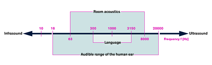
Above: Figure 1. Audible frequency range of the human ear. (Image source: TRACO)
Perception and effect
Humans can hear sound waves in the 16Hz to roughly 20kHz frequency range (Figure 1). However, whether or not a sound causes distraction or irritation depends also upon the perception of that sound in the environment where it is being generated.
An industrial power supply unit that generates audible noise probably does not constitute an actual problem for people, since most people in its vicinity will experience it in the context of other background noises as a normal part of working in factories. Other noises, thanks to their frequency and volume, may also mask the frequencies generated by a power supply, an effect studied in psychoacoustics and used in the compression of audio in MP3s. Such supplies are also typically built into control panels with closed doors that also help to dampen any audible noise that may be generated.
In a different environment, such as an office, the reaction to power supply noise will be significantly different. A whining or buzzing from an electrical device will likely be perceived as being unpleasant and may even raise concerns about its safety.
Causes and background
The magnetic fields: If a current-carrying conductor is located in a magnetic field, it is generally subject to a force. The effect of this force is greatest when the current and magnetic field directions form a 90° angle. In such cases, the impacting force is vertical to the flow of current and direction of the magnetic field. Three fingers of the right hand can be used to determine the direction of this force using Fleming’s right-hand rule (Figure 2).
In the context of transformers and some inductors, an iron core can also suffer from an effect known as magnetostriction, an effect first identified by James Joule in 1842. It causes ferromagnetic materials to change shape or dimension during the process of magnetisation that results from current flowing through the component’s conductor. As well as leading to frictional heating, these tiny changes in material volume often generate audible noise, too.
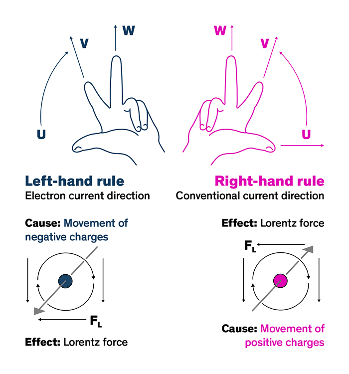
Above: Figure 2. Right/left hand rule. (Image source: TRACO)
Transformers often utilise Fe-Si steel (known as silicon steel) with varying silicon content which helps to increase the electrical resistivity of the iron. Six percent silicon steel provides the optimum level of reduction in magnetostriction but must be traded against increased brittleness.
The piezo effect: A further cause of noise results from the piezo effect. The word ‘piezo’ is derived from the Greek word for pressure. In 1880, Jacques and Pierre Curie discovered that pressure in various crystals, such as quartz, generated electrical charge. They called this phenomenon the ‘piezo effect’ (Figure 3). Later, they noticed that electrical fields can deform piezoelectric materials. This effect is known as the ‘reverse piezo effect’.
The reverse piezoelectric effect causes a length change in these materials when electrical voltage is applied. This actuator effect converts electrical energy into mechanical energy. Changes in voltage also alter the geometric mass of ceramic capacitors, resulting in them acting like tiny speakers that emit pressure waves into the vicinity.
Switching topologies and feedback loops
The drive to ever more efficient power conversion means that switching topologies are being integrated into even the simplest power supply products. The primary switching frequency chosen in such designs will often be selected to lie above the limit of human perception (>20kHz). However, in switching solutions that rely on changing their switching frequency to adapt to changing load and input voltage, this may drop into the audible range in order to maintain optimal conversion efficiency.
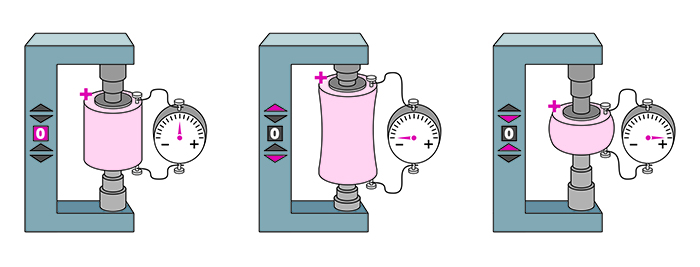
Above: Figure 3. Piezo effect as demonstrated in materials such as quartz. (Image source: TRACO)
In fixed frequency solutions, features such as cycle skipping or burst mode operation can result in a switching pattern that falls into the audible range, despite the switching frequency itself lying above 20kHz. If the solution displays regular switching pulses broken irregularly by periods of two or more skipped pulses, this may indicate issues with the feedback circuit (Figure 4). Here it is worthwhile reviewing the feedback circuit components and the operating region of any optocouplers.
Determining and resolving audible noise issues
With SMPSs becoming increasingly more compact thanks to the push for ever higher power densities, it can be challenging to even determine which component exactly is the audible noise source. Assuming that the design is operating correctly from an electrical standpoint, one approach is to use a non-conductive object, such as a chopstick, to apply light pressure to individual components on the circuit board while the device is operating. Changes or reductions in noise, especially amongst prime candidate components, such as ceramic or magnetic devices, may provide a good starting point.
If there is no safe non-conductive probing device to hand, a rudimentary ear trumpet can be created from a sheet of paper. Rolled up into a cone, the small end’s aperture can be directed toward suspect components to evaluate noise generating sources.
Ceramic capacitors that undergo high dv/dt swings often prove to be audibly noisy and tend to be found in clamp and snubber circuits, as well as in the output stages. To test whether they are the noise source, they can be replaced by capacitors with alternative dielectrics such as metal film, or the series resistance could be increased (Figure 5). Should the audible noise be reduced, a permanent change in component should be evaluated.
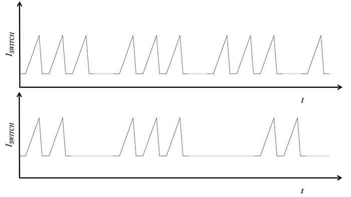
Figure 4. Issues in the feedback circuit can result in irregular pulseless periods in fixed- frequency switching designs. (Image source: TRACO)
Changing clamp circuits to use Zener diodes can also help. Problematic output stage capacitors could be swapped out for a different dielectric or replaced with equivalent value parallel ceramic capacitors if space allows.
If magnetic components are the noise source, first ensure that the input voltage and output load are always within the specified range. Increasing capacitance on the input side can help if the input voltage is sometimes dropping too low. Dip varnishing of transformers, and dip varnished and potted inductors, are one approach to reducing noise. Long core length transformers also tend to resonate more audibly than those of short core length. Where possible, consider changing to an alternative shorter core that can still accommodate the required number of windings.
It should be borne in mind that, for all of the possible approaches highlighted, the repetition of verification and production testing will be highly likely.
Summary
Both the force impact of current-carrying conductors in magnetic fields and the reverse piezo effect of capacitors are primarily responsible for the audible noises emitted by power supply units. Despite advances in simulation, audible noise typically only becomes apparent once a design has been physically built, and sometimes only once a quantity of power supplies has been prepared for pre-production.

Figure 5. The capacitor in the snubber circuit can be swapped out for a metal film type, or a larger resistance can be tried. (Image source: TRACO)
Although most audible noise in power supplies should raise little cause for concern from a perspective of functionality or safety, it can be annoying and even be perceived as a quality issue by customers. By following some of the simple tips provided here, components acting as noise sources can be quickly identified and, using the suggested approaches, be replaced, affixed or changed to minimise or eradicate the errant sounds being generated.
Featured products
| Manufacturer: | Texas Instruments |
|---|---|
| Part Family: | DP83TC811-Q1 |
| Status: | ACTIVE |
| ROHS: | Y |
| PB Free: | Y |
| Manufacturer: | Texas Instruments |
|---|---|
| Part Family: | UCC15240-Q1 |
| Status: | ACTIVE |
| ROHS: | Y |
| PB Free: | Y |
| Manufacturer: | Texas Instruments |
|---|---|
| Part Family: | TMP1827 |
| Status: | ACTIVE |
| ROHS: | Y |
| PB Free: | Y |
| Manufacturer: | Texas Instruments |
|---|---|
| Part Family: | SN74AHC1G02-Q1 |
| Status: | ACTIVE |
| ROHS: | Y |
| PB Free: | Y |
| Manufacturer: | Texas Instruments |
|---|---|
| Part Family: | DLP301S |
| Status: | ACTIVE |
| ROHS: | Y |
| PB Free: | Y |
| Manufacturer: | Texas Instruments |
|---|---|
| Part Family: | TMUXHS221LV |
| Status: | ACTIVE |
| ROHS: | Y |
| PB Free: | Y |