
The real-time study of multi-user MIMO
How a system built from 24 FPGAs, 96 antennas plus a custom 802.11 implementation enables the real-time study of Multi-User MIMO (MU-MIMO) propagation environments. By Patrick Murphy, President, Mango Communications; Chris Dick, Chief DSP Scientist, Xilinx; Ashutosh Sabharwal, Professor, Rice University; Lin Zhong, Associate Professor, Rice University; and Clayton Shepard, Graduate Student, Rice University.
MU-MIMO is a wireless communications technique that leverages multiple antennas at infrastructure nodes, like basestations and access points, to serve many clients simultaneously. MU-MIMO is an integral part of upcoming wireless standards and is expected to deliver significant improvements in the performance of busy networks.
It is envisioned that with each new generation of wireless systems, the number of antennas at basestations will continue to grow, eventually leading to ‘massive MIMO’ systems. The massive-MIMO approach extends the number of antennas at MU-MIMO basestations to tens or hundreds, seeking to improve performance while possibly simplifying the basestation’s signal processing. One scalable massive-MIMO technique is known as conjugate beamforming, and early implementations of this strategy show the potential for real-world gains.
MU-MIMO techniques rely on accurate knowledge of the wireless propagation environment. An MU-MIMO infrastructure node can serve multiple users simultaneously only if it has accurate and recent measurements of the wireless channel to each user. Gathering this channel information in real time is challenging, and the performance impact of stale or inaccurate channel information can be severe.
An integrated system for massive-MIMO channel characterisation enables researchers to study the dynamics of channels in real time. The system uses the Xilinx FPGA-based Wireless Open-Access Research Platform (WARP) hardware platform and Mango Communications’ 802.11 Reference Design at its core, scaled up to 24 FPGAs connected to 96 antennas using the Rice University Argos platform. A custom Python framework developed by Mango Communications controls and gathers data from every node in the array in real time. This combination of Mango- and Rice-developed tools provides deep visibility into the wireless stack, including the raw channel data necessary for characterising massive MIMO.
A key feature of the custom 802.11 implementation by Mango Communications is its ability to stream low-level baseband parameters, like AGC gains, channel estimates and raw packet contents (even packets with errors), from all receiving antennas in real time.
System components
The WARP is a scalable and extensible programmable wireless platform, built from the ground up to prototype advanced wireless networks. WARP combines high-performance programmable hardware with an open-source repository of reference designs and support materials.
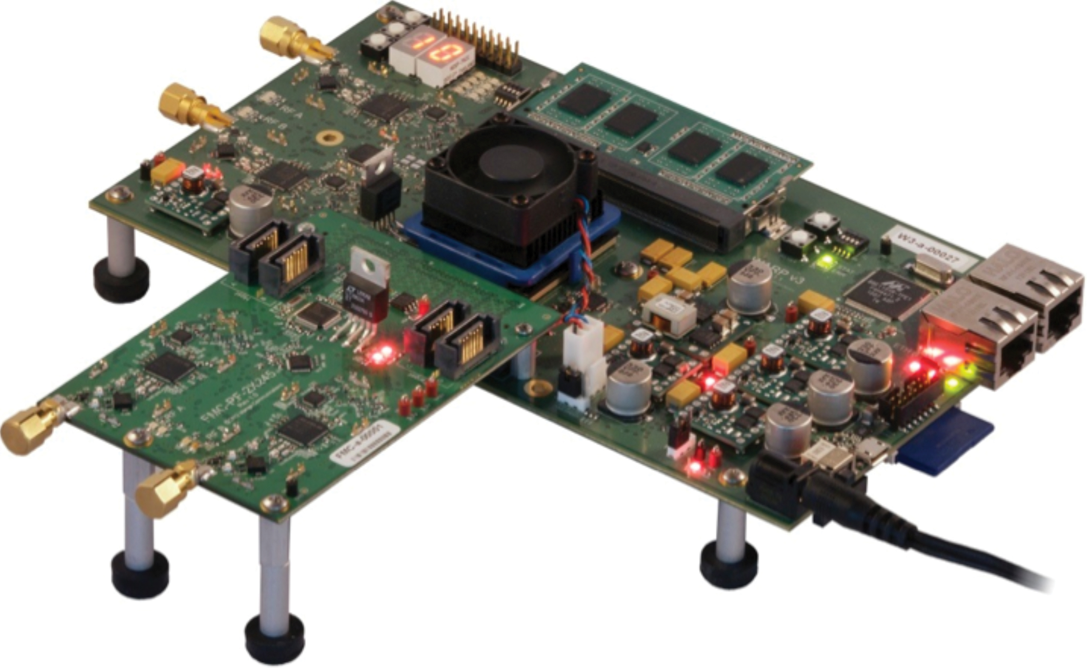
Figure 1 - The WARP v3 hardware with dual-radio FMC module provides a large FPGA, four RF interfaces, memory and two Ethernet connections.
A central component in the system for measuring massive-MIMO channels is Mango Communications’ WARP v3 hardware platform; designed for rapid, real-time prototyping of novel wireless designs. The hardware integrates a high-performance Xilinx Virtex-6 FPGA, two flexible RF interfaces and multiple peripherals, including DDR3 DRAM and two 1Gb/s Ethernet interfaces. The WARP v3 board can be extended to four RF interfaces with Mango’s dual-radio FMC module. This hardware configuration, shown in Figure 1, provides four fully programmable RF interfaces with independent digital baseband connections to the FPGA.
To study massive-MIMO systems, it’s necessary to co-locate multiple WARP v3 nodes with shared power, clocking and Ethernet connectivity. This requirement has been addressed by the Rice University Argos project. The Argos v2 array is a collection of 24 four-antenna WARP v3 nodes, pictured in Figure 2. The Argos array is designed to support a wide variety of massive-MIMO experiments and is perfectly suited to gathering channel measurements simultaneously across all 96 array antennas.
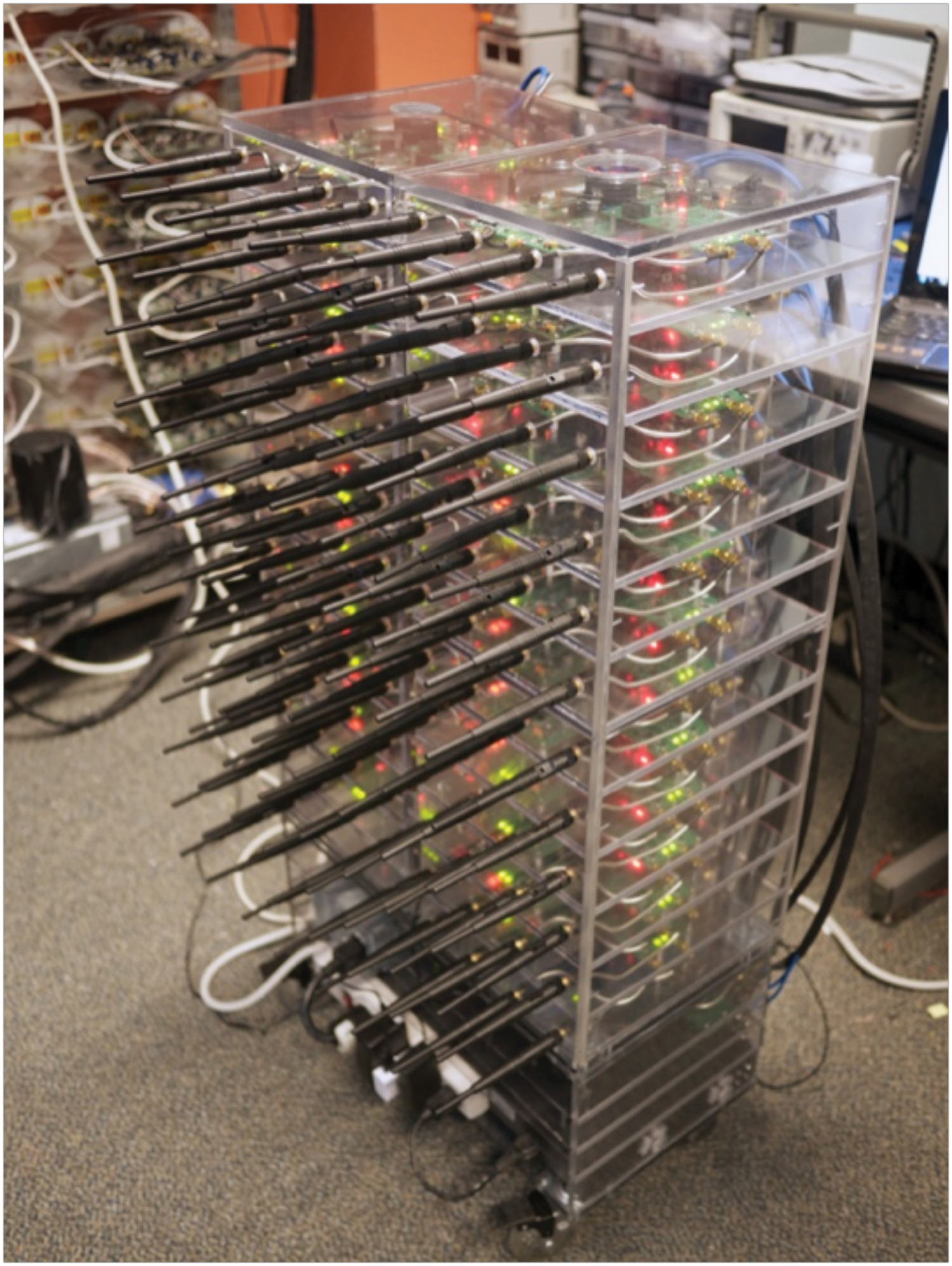
Figure 2 - The Rice University Argos v2 array combines 24 quad-radio WARP v3 nodes with shared clocking and Ethernet connectivity.
The FPGA on each WARP v3 node in the Argos array provides significant processing power close to the RF interfaces. In a massive-MIMO configuration like Argos, there is a tremendous amount of data to process. For example, when receiving 40MHz of bandwidth, each RF interface on WARP v3 generates a 960Mb/s sample stream (dual 12-bit 40MS/s ADCs). The full Argos array generates 96 times this amount - far more than can be streamed to a PC and processed in real time. Instead, the system uses FPGAs to locally process the data in real time and significantly reduce the burden on the upstream processors. For the massive-MIMO channel-characterisation design real-time processing is very important, as it allows the design to continually measure channels and reliably observe sub-millisecond variations in channel characteristics.
The custom FPGA design that performs this processing is the Mango Communications 802.11 reference design for WARP v3; a real-time FPGA implementation of the 802.11a/g Medium-Access Control (MAC) layer and PHY layer. The design can interoperate with standard WiFi devices, acting as an AP (serving WiFi clients), a client (accessing a WiFi AP) or a monitor (a receive-only passive observer of network activity).
Figure 3 illustrates the reference design architecture. The design uses two Xilinx MicroBlaze cores to implement the high- and low-level MAC protocol in software. The MAC connects to two FPGA cores, which implement the PHY transmitter and receiver. We implemented these PHY cores in Xilinx System Generator. The transmitter core implements a complete bytes-to-waveform pipeline. It reads a packet payload from the MAC, creates the OFDM waveform and drives the waveform to the RF interface DACs. This pipeline includes encoding, scrambling, interleaving, IFFT and preamble insertion. The MAC specifies the modulation and coding rates per packet; all eight data rates specified in 802.11a/g are supported.
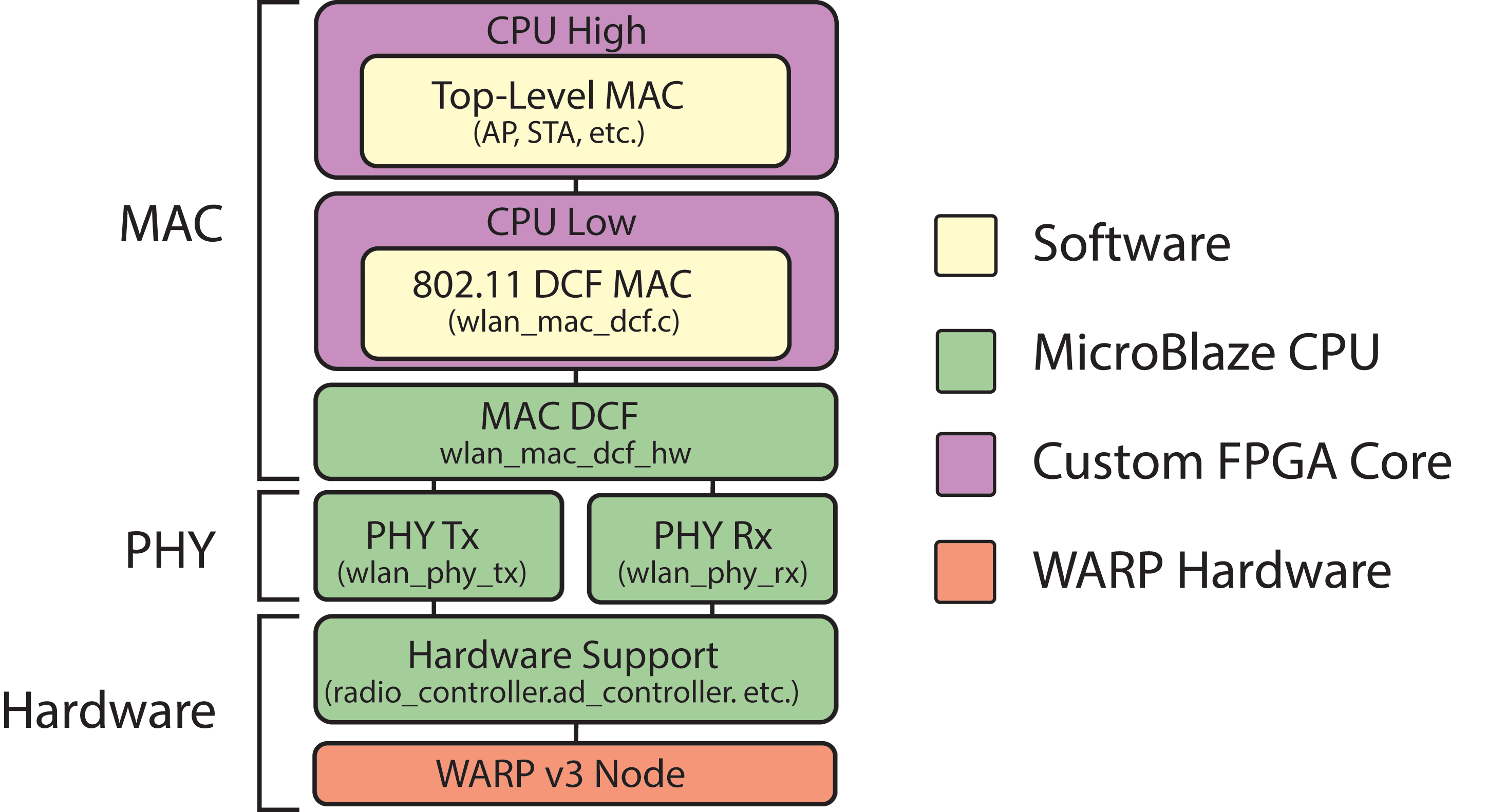
Figure 3 - The Mango 802.11 Reference Design architecture includes two Xilinx MicroBlaze CPUs for the MAC and custom System Generator cores for the PHY transmitter and receiver.
The receiver design implements the full waveform-to-bytes pipeline, including AGC, synchronisation, FFT, channel estimation, equalisation, detection and decoding. The receiver configures its demodulation and decoding blocks automatically per packet using the RATE value in the packet’s SIGNAL field. The receiver decodes packets of any rate fast enough to meet the standard’s strict Rx-to-Tx turnaround requirements for transmitting an ACKnowledgement (ACK) in response to a reception.
One feature of the receiver design that is central to characterising massive-MIMO channels is the channel-estimation subsystem. In a standard OFDM receiver, the channel estimator produces a complex channel coefficient per subcarrier. The equaliser uses these estimated coefficients to correct the channel’s amplitude and phase degradations for each received data symbol. The design additionally saves a copy of the channel estimates for every received packet to an on-chip memory area. The MAC treats these channel estimates as extra metadata about the received frame, along with standard information like Rx power, AGC gain selections, checksum status and antenna selection. The channel estimates are then copied to the higher-level MAC for further processing. The characterisation platform gathers these estimates from every packet received by every node in the Argos array to assemble its real-time view of the massive-MIMO propagation environment.
WARPnet experimental framework
The final piece for the massive-MIMO characterisation system is a framework, dubbed WARPnet, for running experiments with large networks of WARP nodes. WARPnet is a custom Python package that uses a dedicated control connection to multiple WARP nodes. The framework allows a Python script running on a PC to remotely configure experiment parameters and retrieve experimental data, all in real time. WARPnet interacts with the Mango 802.11 Reference Design via the secondary Ethernet connection on each WARP v3 board. The upper MicroBlaze device processes the WARPnet commands, giving the framework direct access to the node’s high-level MAC state and all data passed up from the low-level MAC and PHY.
Conjugate beamforming is an alternative MU-MIMO technique. In this approach, the basestation seeks to maximise the good signal power delivered to each client device without actively minimising the interference power. In theory, the conjugate beamforming approach of increasing SINR (Signal and Interference to Noise Ratio) at each user by maximising signal power (the ’S’ in SINR) while ignoring interference power (the ‘I’ in SINR) improves with an increasing number of antennas. Further, the conjugate beamforming calculation of each transmit antenna’s waveform does not require knowledge of any other antenna’s channel characteristics. Together these factors make conjugate beamforming well suited to massive-MIMO systems, where a basestation has many more antennas than users.
Consider the classic expression for Shannon channel capacity, C = log(1+SINR). The capacity of the wireless channel, in bits/second/Hz, grows logarithmically with the SINR. Conjugate mult-iuser beamforming has two competing effects when the system adds more users and antennas. First, the presence of multiple antennas allows for an increase in received signal power, since each antenna can rotate its phase such that transmissions are constructively combined at the users’ receivers. Second, the presence of multiple transmissions to independent users creates an increase in interference power. The superimposed interference signals combine randomly. As the number of antennas increases, the growth in constructively combined signal power outruns the randomly combined interference power, increasing overall SINR.
The 24 WARP v3 nodes in the Argos array are configured with a custom version of the Mango 802.11 Reference Design. This version operates in receive-only monitor mode, attempting to receive packets on all four of the node’s antennas. For every packet reception, the node estimates the complex channel coefficient for each subcarrier, decodes the packet and sends the packet header and channel estimates via Ethernet for analysis. This processing flow is implemented in all 24 nodes in the array, with all nodes operating in parallel.
To communicate with standard WiFi devices, the channel-measurement platform must also implement a standard 802.11 access point. Another WARP v3 node is used for this purpose, running the Mango 802.11 Reference Design in AP mode. This AP node serves as the 25th node in the Argos array. The AP advertises an open WiFi network, accepts associations from commercial WiFi devices and serves internet access via its primary Ethernet connection.
Real-time analysis
The final component of the massive-MIMO channel-measurement platform is a custom application that gathers the array-channel estimates, computes achievable multi-user capacities and displays the results in real time. It was developed in Objective-C, using native UDP sockets to interface with the WARP v3 nodes in the array and OS X graphics frameworks for plotting results.
The application has two primary views. The first displays the raw channel magnitudes that each array antenna gathers for every subcarrier, 4,992 data points in all (52 subcarriers x 96 array antennas). This view is a raw display of the channel data gathered by the array and serves primarily to convey the wide range of channel values observed by individual array antennas.
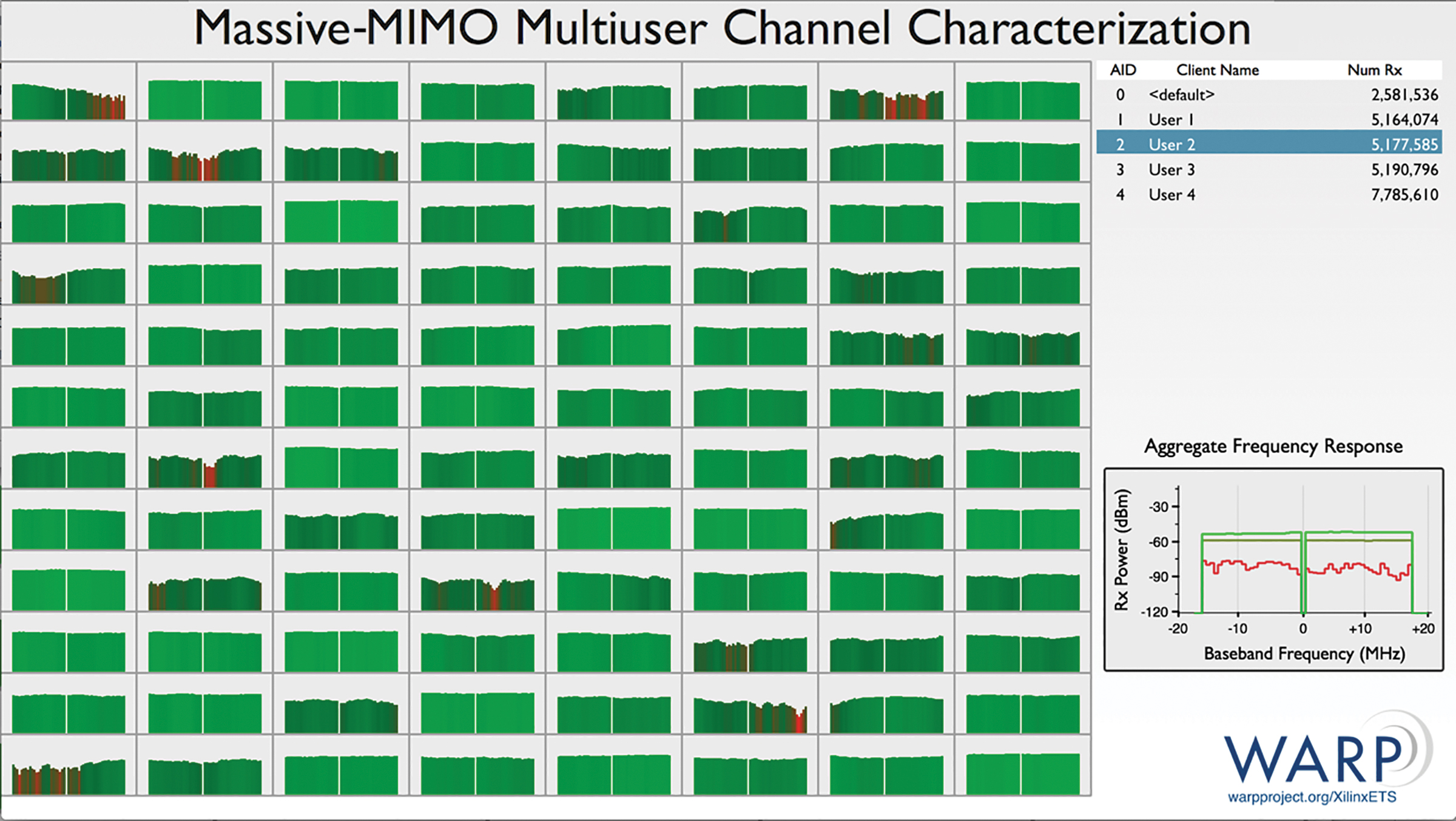
Figure 4 - Estimated network capacity for single-user and multi-user techniques were calculated from real MU-MIMO channel measurements the array had gathered, as displayed by the custom analysis application.
The application’s second view displays results of capacity calculations based on the array’s channel estimates, illustrated in Figure 4. Two capacity calculations are performed; the first plots the capacity to each user vs. the number of array antennas used. Each line on this plot approximates the achievable downlink capacity to a single user assuming the array used a subset of its antennas in a traditional, single-user beamforming configuration. The decreasing slope of each capacity curve with increasing antennas clearly demonstrates the diminishing benefit of many antennas with traditional, single-user wireless techniques.
The second plot shows the total network capacity if the array implements downlink multi-user beamforming techniques using a subset of its antennas. The trends on the four plots clearly highlight the benefit of additional antennas when multi-user techniques are employed. The increasing slope when additional users are served highlights the ‘outside the log’ (often labeled ‘pre-log’ in MIMO literature) gain in network capacity with multi-user beamforming.
Product Spotlight
APV1111GVY
Panasonic

Panasonic PhotoMOS® Photovoltaic MOSFET High-Power Drivers
| SKU: | |
|---|---|
| Stock: | 3490 |
| Cost: | $3.95 |
