
Better design tools are needed for MCU-based devices
The rise of configurability in MCU-based devices has increased the need for better graphical design tools.
By Mark Saunders, Cypress Semiconductor.
Programmable devices with embedded CPU cores provide an effective means for addressing a wide range of design challenges that are difficult or costly to solve with just hardware or software alone. These devices combine digital and analogue hardware resources that can be reprogrammed to provide the exact functionality needed. But the devices offered by today's semiconductor vendors are as varied, and interesting, as the problems they solve. Cypress Semiconductor's PSoC, for example, integrates an ARM CPU core with the usual MCU peripherals and arrays of programmable digital and analogue blocks. This configurability allows the user to customise the PSoC device to perfectly suit specific applications. XMOS takes a different approach with its xCORE technology, integrating multiple processor ‘tiles’ to create a very powerful and flexible device. Whether the device is a multi-core CPU or a re-programmable SoC, developers are going to need high-quality, easy-to-use design tools to eliminate the complexity typically associated with programmable logic. PSoC Creator from Cypress Semiconductor, for example, was designed specifically to make this task easy. Rather than forcing engineers to complete electrically perfect circuits, PSoC Creator allows you to draw only the relevant part of the design - just like one would on a whiteboard. It then figures out the best placement and routing of peripheral blocks (which are called components), sets up the required clocking and power configuration, and optimises the design.
Being a mixed-signal device, PSoC includes integrated DAC and these can be used to output a voltage (or current) to a pin or somewhere else on the device. Engineers can connect a DAC to a pin by dragging and dropping the components onto a sheet, called a schematic and wiring them together. It takes just a few seconds to locate the components and copy them into the schematic.
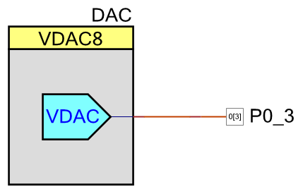
Figure 1 - Connecting a DAC output to an analogue pin with PSoC Creator
Notice that there are no ‘inputs’ to the DAC; no power line, no Vref input, no scary bus interface, just a single voltage source that is wired to a pin (the pin is equally simple, too). In reality, PSoC pins can support a wide combination of GPIO, SIO and analogue functionality with various drive modes, plus enable and synchronisation features. But the analogue pin used here has already configured the physical pin in just the way needed, so there is no need to be concerned with how to safely turn those features off without impacting the signal from the DAC.
Both PSoC Creator and the XMOS xTIMEcomposer Studio IDE ship with a fully-validated suite of peripherals – for example, ADC, DAC and amplifiers; UART and I2C, PWMs and Timers – which are much easier to use than the raw IP blocks found in traditional schematic capture tools. In these tools, the peripheral’s implementation details are abstracted away and designs are error-free the first time. Users are able to select functionality in a parameter editor and the tool determines the device configuration needed to achieve your requirements. Simply drop the required function into the project and make your selections in the editor.
Natural APIs
Consider a UART. This is typically a firmware-oriented component and so the editor presents the configuration options in a way that is natural to those engineers. No option is given for a clock input and over-sampling rate. The only request is what baud rate you require and the tool automatically creates a clock source that will supply the appropriate frequency to the component.
Programmable devices with integrated CPUs need tools that also integrate the hardware and software development tasks. One of the problems faced by silicon-centric tools is that software engineers are typically forced to use tools they do not particularly like, along with having to deal with raw memory and register-level interfaces to the peripherals. Without the right software tools, a programmable SoC empowers the hardware designer to the detriment of the software team. The hardware schedule is greatly accelerated and risk is minimised, especially when compared to an ASIC flow. However the burden of getting things to work is really just being pushed onto the software development team.
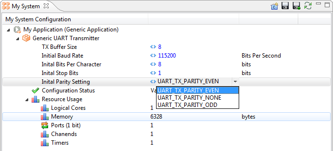
Figure 2 - Configuring a UART is similar in both PSoC Creator and xTIMEcomposer
Another example of a graphical design tool is the Digital Application Virtual Engineer, or DAVE, from Infineon Technologies. Like PSoC Creator, DAVE allows users to select from a library of components, or Apps, to configure and build the hardware. Most components have a software interface (the exceptions are low-level components like LUTs, logic gates and multiplexers) that make it easy to drive the peripherals from C code. Rather than presenting a set of memory-mapped registers with esoteric bit fields and (often) undocumented side-effects, components bundle the typical functionality into C-language API calls. To start a Timer running you call an API like Timer_1_Start(). (You’ll never guess how to stop it.) Reading the current value of the timer is achieved by using the return value from Timer_1_ReadCounter(). Once you get used to the style of the APIs, you can often guess the API names for a component that you have never used. If you don’t guess right, a complete datasheet is always available from the customiser dialogue or by right-clicking on the component.
In both PSoC Creator and DAVE, component APIs are provided as source code, making debugging the software-hardware interaction very simple. There are no libraries to include in the build and there is no need to go hunting through web pages to find device drivers (that always seem to be for another device anyway). There are no restrictions on where breakpoints are placed or what code can be stepped through while debugging. One rarely needs to switch to an assembler view when troubleshooting a component’s behaviour.
Concurrent design
Today, development is often split into hardware and software teams with the two teams often not located in the same building or country. This could present a problem when selecting the project tools, debug solutions, maintenance contracts and so on. Switching to a new software development environment is often impractical as they are usually very well established parts of the engineering development flow with high levels of integration into company systems, for example source control and documentation management.
A better approach in these environments is to consider hardware design software as a ‘chip configuration’ tool, rather than a replacement IDE. Hardware engineers can use the tool to generate a design and generate all the configuration data and APIs. The software team merely needs to integrate these files into their IDE of choice, such as IAR’s Embedded Workbench or ARM’s MCU DevKit and follow a familiar edit-build-debug cycle. The hardware team is free to use PSoC Creator or DAVE to build test benches for their designs and the boards on which they are used. It’s even possible to create board support packages or hardware abstraction layers to share with the software team, which makes interaction with the device as easy and error-free as possible.
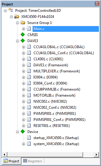
Figure 3 - A screenshot of the µVision IDE from ARM, showing a DAVE3 Pack in the Project Explorer window
This integration with traditional software IDEs is really important in team-based development. Indeed, it is so important to users of ARM Cortex M-class devices that ARM developed CMSIS-Pack, an extension of their successful CMSIS (Cortex MCU Software Interface Standard) hardware abstraction. CMSIS-Pack is a means of describing a device to an IDE, making it possible for the IDE to support software development without having to build the functionality into their product. The pack describes the source, header, and library files, plus documentation, flash programming algorithms, source code templates, and example projects to the IDE so that it can provide a world-class development environment without the need for a new revision of the software.
DAVE and PSoC Creator embrace the CMSIS-Pack standard by including a function to generate a pack file for the customer’s design. This makes the integration between the hardware configuration tool and the software IDE natural and error-free. The hardware engineer simply generates the pack file and shares it with the software team. Updates to the hardware are instantaneous – no waiting for the new board to arrive - because the new configuration is simply loaded directly into the software project.
When new hardware is required, the process of handing over an updated board to the software engineers is infamously problematic. A machine-generated CMSIS-Pack takes away a lot of the time-consuming job of updating software projects to match the new board. To alleviate this problem even further PSoC Creator generates a datasheet for the user’s actual design. The device configuration information, clock setup, pin selections, and descriptions of all generated component APIs can be output into a single datasheet file, straight from the tool. There is no risk of a cut-paste error or a forgotten piece of information because the document is machine-generated. It is clear that the traditional MCU is being replaced with a new breed of configurable device. The configurability takes many forms, from devices with simple pin multiplexing, to multi-core solutions like xCORE, up to PSoC that enable user configuration of powerful digital and analogue arrays.
In order to extract the most from these devices, engineers need more from their development tools. In addition to standards, like CMSIS, that support interoperability between hardware and software teams, they need component-level design and configuration interfaces that focus on what the component does, rather than how it is implemented in a given device. Most importantly they need tools that take advantage of all these technologies without tying the developers to a single development tool for all steps of the process.
Product Spotlight
APV1111GVY
Panasonic

Panasonic PhotoMOS® Photovoltaic MOSFET High-Power Drivers
| SKU: | |
|---|---|
| Stock: | 3490 |
| Cost: | $3.95 |
