
Single IC power management battery maintenance for 48V supplies
Elegant, single-IC power management solutions are readily available for many portable devices, such as smartphones or tablets, which operate at low voltages and low power levels. Power management solutions for high power and high voltage systems, such as those required for many industrial or medical devices, generally require cumbersome, specialised discrete component solutions. In these environments, the LTC4020 simplifies power management by incorporating advanced power management functions into a high voltage and high power single-IC solution.
It features a four-switch buck/boost DC/DC power converter, support for optimised battery charging, and Linear Technology’s proprietary PowerPath system/battery power management functionality. Power distribution is managed between the system input supply, the back-up battery, and the converter output in response to load variations, battery charge requirements and input power limitations.
The single-inductor DC/DC buck/boost controller can accept input voltages up to 55V and produce voltages that are lower, higher, or the same as the input voltage. The onboard battery charger can be configured to provide a Constant-Current/Constant-Voltage (CC/CV) charge profile optimised for lithium-based batteries, a three-stage, lead-acid battery charge profile, or a modified timer-terminated CC algorithm, which is similar to the lithium profile but does not incorporate low voltage pre-condition and charge cycle restart functions.
CC charging bends the rules
When the LTC4020 is configured in the charge mode optimised for lead-acid batteries, the regulation voltage during absorption charging is 120% of the typical battery system voltage, or 14.4V for a 12V lead-acid battery. The built-in lead-acid charge algorithm cannot be used for a 48V system battery, since the absorption charge voltage would exceed the operating maximum voltage for the controller. This can be addressed by implementing a high current float charger using the CC charge algorithm.
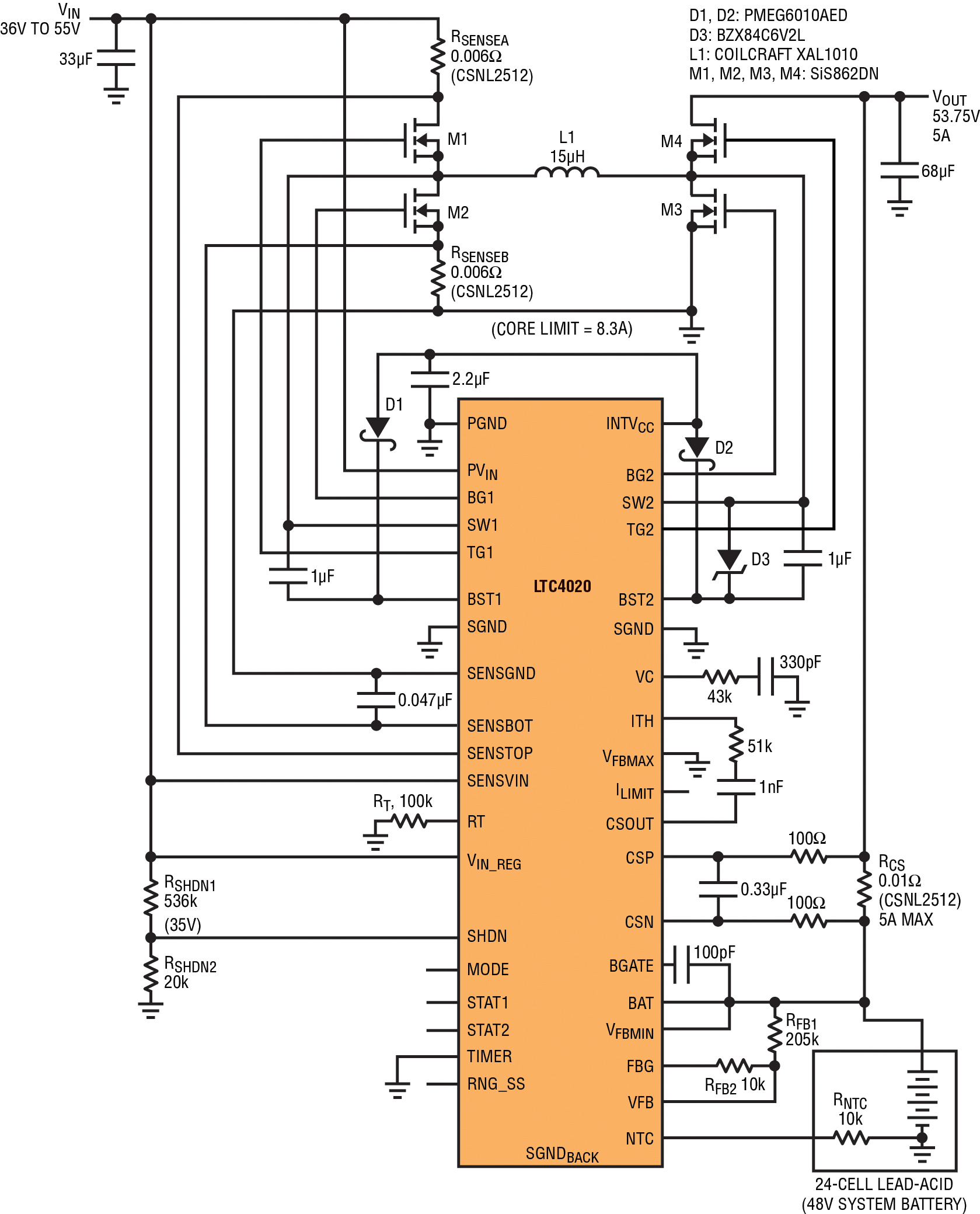
Figure 1: The 36 to 55V to 24-cell lead-acid (48V) float charger/system supply.
The CC charge algorithm is enabled by leaving the Mode pin unconnected. A feedback resistor divider programs the desired battery float charge voltage, corresponding to VFB = 2.5V. The CC charge algorithm enables the full programmed charge current until the float regulation voltage is achieved. While maintaining the float regulation voltage, a lead-acid float charger must be able to continuously source current into the battery, so the charge function cannot terminate. CC charge mode can accommodate this by setting Timer = 0V, which disables the timer function and thus disables charge termination, so the charge cycle will continue indefinitely.
Battery back-up
Figure 1 shows an LTC4020 configured as a 48V system supply with an integrated-battery float charger. The central component is an average current-mode buck/boost DC/DC controller, employing four external NFETs as switching elements, which provides 265W of available output system power.
The converter operates from a 36 to 55V input supply, with the converter limited to 8.3A of average inductor current. The converter current limit is programmed by two 6mΩ sense resistors (RSENSE1 and RSENSE2) placed in series with SiS862DN switching FETs M1 and M2. The DC/DC converter supports at least 5A at its output over the entire operating voltage range.
RSHDN1 and RSHDN2form a divider at the SHDN pin, which sets the input shutdown voltage at VIN = 35V, disabling the DC/DC converter and battery charger functions when the input is below 35V, so full load current is available whenever the supply is enabled. The SiS862DN switch FETs used here have a typical QG of about 10nC each, so with the operating frequency set to 250kHz by resistor RT, the QG (total) fO at VIN = 55V falls within the LTC4020’s specified INTV CC pass element SOA guidelines.
The IC charges and maintains a 24-cell (48V) lead-acid back-up battery using a CC/CV voltage charge profile. The maximum battery charge current is programmed by RCS to 5A, which is available until the full-charge float voltage of 53.75V is achieved. The battery voltage is monitored by a resistor divider (RFB1 and RFB2), which programs the full-charge float voltage of 53.75V (or 2.24V/cell). This divider is referenced through the FBG pin, which is shorted to ground when the LTC4020 is operating, but becomes high impedance when the IC is disabled, reducing the parasitic load on the battery.
Preferential power to the system load and battery charging functions means the system load is always prioritised over charging power, so battery charge current is reduced when necessary during periods of heavy loads. Should the system load exceed the capabilities of the DC/DC converter, battery current will change direction and load current will be sourced from the battery to supplement the converter output.
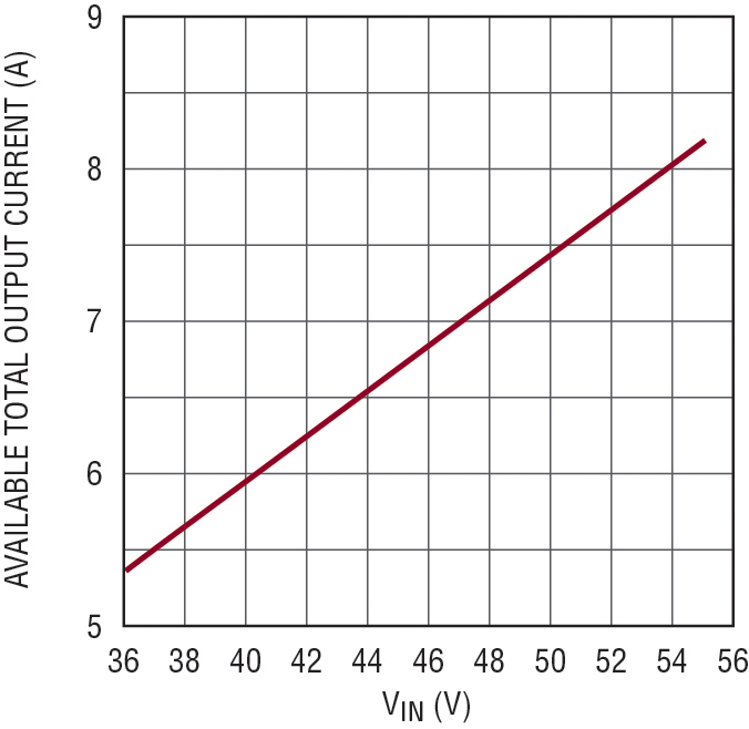
Figure 2: Available converter output current (system load current + battery charge current) vs input voltage.
When the VIN supply is disconnected, all LTC4020 functions cease and the battery supplies require power to the output. Reverse conduction from the battery through the converter is blocked by the switch FET M4, the battery voltage monitor resistor divider is disconnected via pin FBG, and total battery current into the IC is reduced to less than 10µA, maximising battery life should a no-load storage condition be required.
Product Spotlight
APV1111GVY
Panasonic

Panasonic PhotoMOS® Photovoltaic MOSFET High-Power Drivers
| SKU: | |
|---|---|
| Stock: | 3490 |
| Cost: | $3.95 |
