
Improve light-load efficiency of a PFC converter
Economic and environmental concerns are forcing the power supply industry to improve efficiency across the entire load range, not just at heavy load, but methods to improve light-load efficiency are developing. By Bosheng Sun, Systems Engineer, Texas Instruments.
The efficiency of a power conversion system is becoming ever more important with today’s power needs. The efficiency levels defined in the 80 PLUS efficiency specification adds higher efficiency standards from Gold to Platinum and Titanium. It becomes a design challenge for power converter technology when high efficiency is required over a wider operating range.
PFC is used at the front-end power supply with input power of 75W or greater. It forces the input current to follow the input voltage, so that any electrical load appears like a resistor to the voltage source that powers it. With the help of new semiconductor devices and new control methods, PFC has achieved very good efficiency at middle to heavy load. However, when reduced to light load, efficiency deteriorates significantly.
The typical PFC efficiency curve is shown in Figure 1. Notice how much lower efficiency becomes at light load. This is because the switching loss, driving loss, and magnetic core losses along with reverse recovery loss of semiconductor components become dominant at light load. These losses are almost independent of the load, the efficiency curve shows a steep fall off as the load decreases below 20% of the full load.
Improving PFC light-load efficiency is challenging and many papers have been written on this topic; this article summarises four effective, but easy to implement methods on how to improve PFC efficiency at light load.
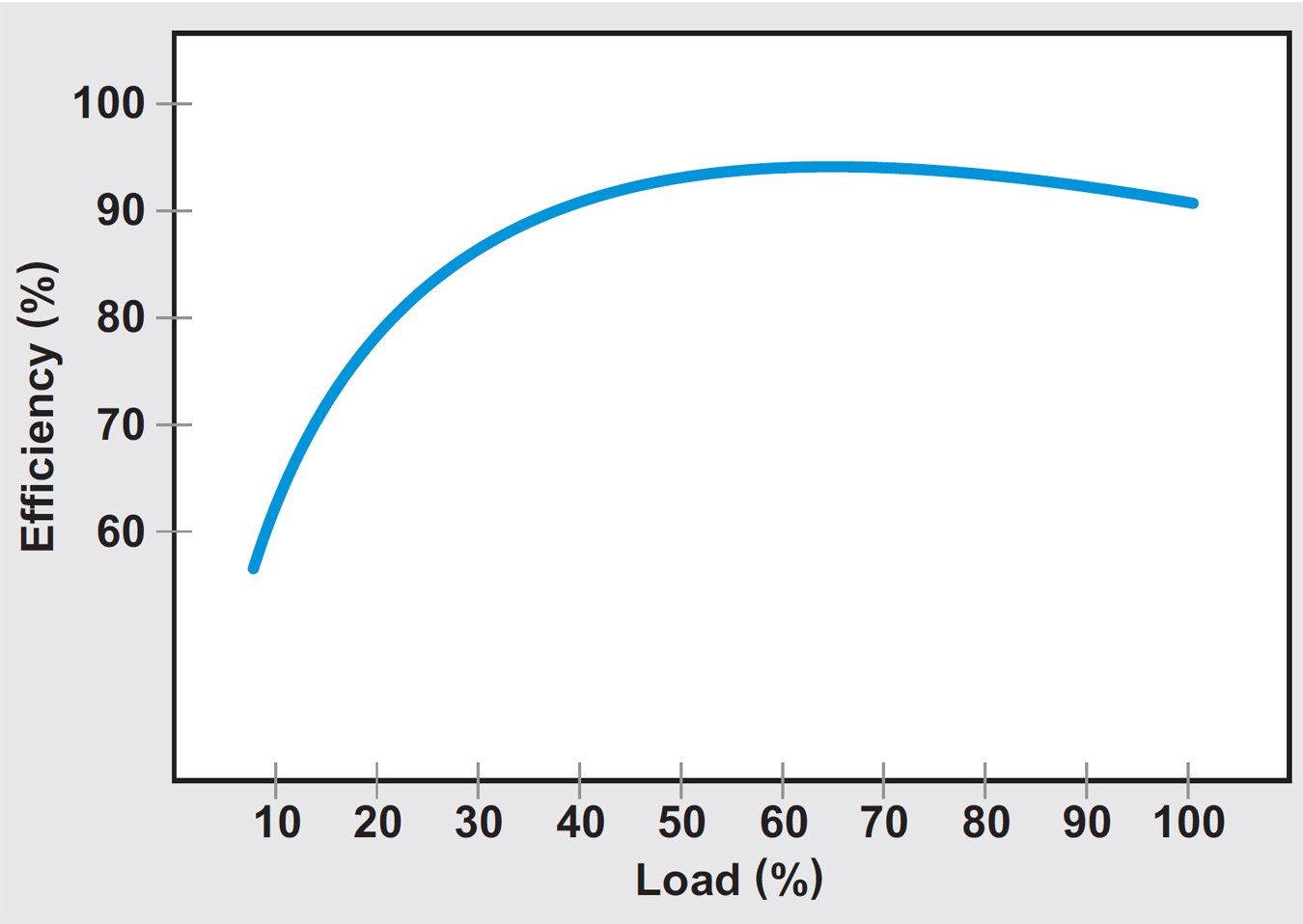
Figure 1 - Example of a typical PFC efficiency curve
Methods for improving PFC
Reducing the switching frequency and output voltage is a simple and commonly used method for improving PFC light-load efficiency. Reducing the switching frequency can reduce both switching and driving losses. On the other hand, reducing PFC bus voltage can improve the subsequent DC/DC stage efficiency, thus, the overall efficiency is improved. Since the load is low, reducing the switching frequency and bus voltage almost does not affect power supply performance.
When PFC enters zero-load condition, the control loop generates very tiny PWM pulses, or even zero PWM pulses. The MOSFET turns on for one or more pulses, then turns off for the next one or more pulses. This type of skipping is called PWM pulse-skipping and PFC enters a natural burst-mode. The natural burst-mode improves efficiency at zero load. However, once the load increases, the natural burst-mode disappears.
A new burst-mode or AC cycle-skipping, can force PFC to burst deeper even at a heavier load. In this method, when the load is reduced to less than a pre-defined threshold, depending on the load, one or more AC cycles are skipped by PFC. In other words, PFC turns off for one or more AC cycles, and turns back on for the next AC cycle. The turn on/turn off instance is at the AC zero-crossing, such that the whole AC cycle is skipped. Moreover, since PFC turns on/off at a current that equals zero, less stress and ElectroMagnetic Interference noise are generated.
To maintain the output voltage ripple within a specified range, the number of AC cycles to be skipped is reversed proportional to the load. The lesser the load, the more AC cycles will be skipped. A look-up table can be generated between load and number of cycles to be skipped, such that AC cycles can be skipped as many as possible. Figure 2 shows four different AC cycles skipped at different loads. Channel 1 is AC voltage, and channel 4 is AC current.
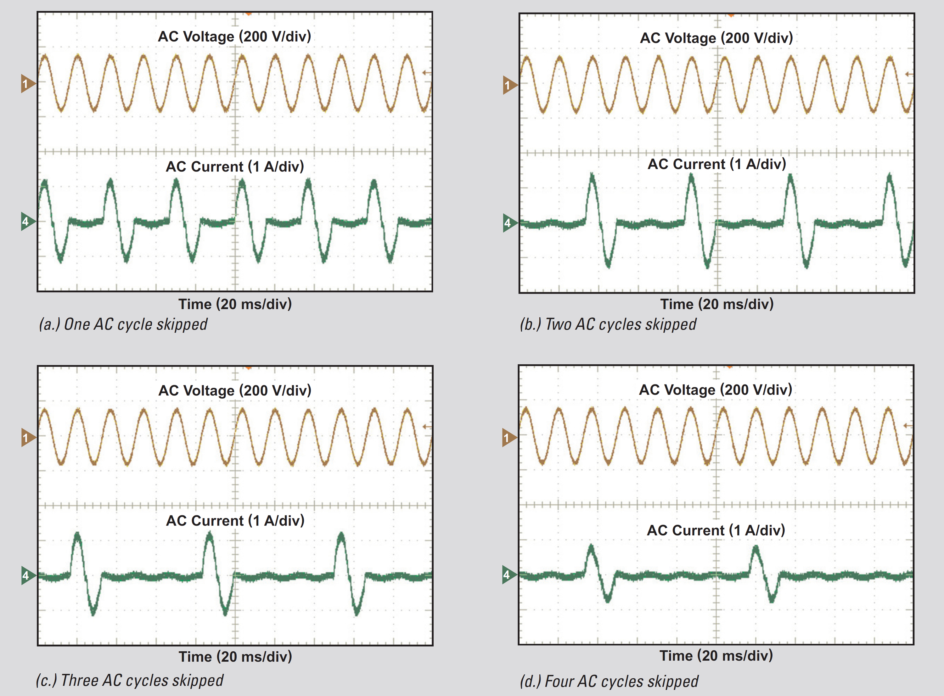
Figure 2 - Four images showing AC cycles being skipped at different loads
Once PFC turns off, all the switching, driving, and reverse recovery losses are reduced to zero, and the power loss is just for the PFC stand-by power. When PFC turns on, since it needs to compensate for the turn-off period, it delivers a large amount of power, which is more than the average value. Essentially, this operates the PFC either at middle load, or completely shuts off. Since efficiency is much better at middle-load than at light-load, light-load efficiency is increased. Figures 3 show the efficiency improvements with this special burst-mode.
Note that when PFC turns off to skip AC cycles, both the current loop and voltage loop needs to be frozen. Otherwise, the integrators in these loops build up. When PFC turns back on, the build-up integrator generates a big PWM pulse, which can cause a large current spike.
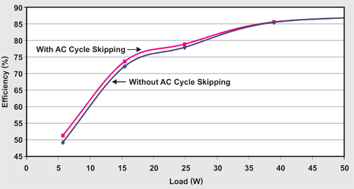
Figure 3 - Efficiency comparison with AC cycle-skipping (pink) and without (blue)
To determine whether or not the PFC enters light-load, the load information needs to be obtained. Normally there is no current sensor at PFC output, therefore, directly measuring the output load is not feasible. However, the PFC voltage loop output is proportional to a load if VIN is fixed, therefore it can be used as a rough indicator to determine whether or not PFC enters light-load. To precisely determine the number of AC cycles to be skipped based on load, such that the output voltage ripple is maintained within a specified range, accurate load information is required. Since current shunt measuring input current for PFC current loop regulation already exists, the input power of a PFC can be measured. This accurate input power information can be used to precisely adjust the number of AC cycles to be skipped.
A big concern of this approach is the output voltage drop during load transient. Assuming a load step up occurs when the PFC is off, VOUT may drop too much. To address this issue, VOUT is compared with a predefined threshold through a comparator. Once VOUT is below this threshold, PFC immediately jumps out of burst-mode, AC cycle-skipping is disabled, and PFC enters normal operating mode. PFC will handle transient response as if there is no such special burst-mode. Figure 4 is a load transient from 0 – 100 percent during AC cycle-skipping, VOUT drop during transient is only 27V, which is very normal for a 360W PFC.
.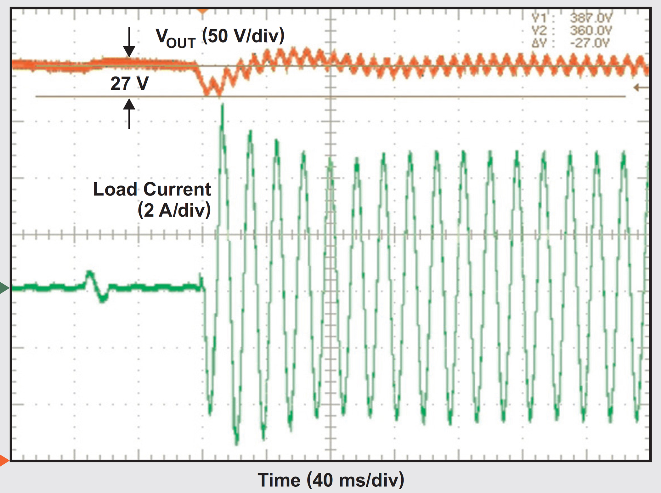
Figure 4 - Load transient from 0-100% during AC cycle-skipping. Channel 1 is VOUT, Channel 4 is AC current
Valley switching
When PFC enters light-load, the inductor current becomes discontinuous, and PFC operates at Discontinuous Conduction Mode (DCM). In DCM, once the boost inductor current declines to zero, the boost inductor resonates with PFC MOSFET’s parasitic capacitance. If the instantaneous AC input voltage is lower than half the PFC output voltage, the MOSFET’s VDS can resonate to zero volts; if instantaneous AC input voltage is higher than half the boost output voltage, the MOSFET’s VDS does not resonate to zero volts. In the next switching cycle, if the MOSFET turns on at the instant that VDS is zero or at its resonant valley, then Zero Voltage-Switching (ZVS) or valley-switching can be achieved. Switching loss is significantly reduced with ZVS, or valley switching. As a result, efficiency is improved.
However, traditional PFC operates with a constant switching frequency, and the turn-on instance of the next switching cycle is fixed. Therefore, at the moment when the MOSFET turns on, the MOSFET’s VDS may already resonant to its peak, which causes hard switching and the switching loss is high. Texas Instruments has developed a novel control method such that when PFC enters DCM, the MOSFET always turns on at the moment VDS resonates to zero or at its valley, this can improve PFC light load efficiency. A test result is shown in Figure 5.
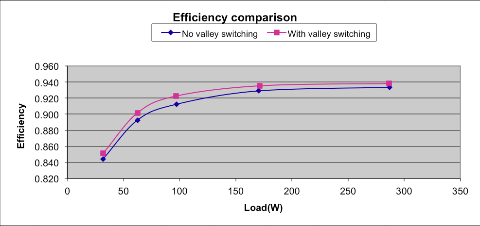
Figure 5 - PFC light-load efficiency improvement with ZVS/valley-switching
Phase-shedding
For high power levels, two PFC stages can connect to the same bridge rectifier and operate at 180° out-of-phase. This is called two-phase interleaved PFC. By controlling two phases with inductor currents of 180° out-of-phase, both input and output current ripple can be reduced. As a result, a smaller EMI filter can be used, which reduces material costs. However, since two PFC stages are operating at the same time, switching and driving losses are doubled. This is not a problem at middle-to-heavy loads since these losses are minor compared to the load. However, they become dominant at light-load. On the other hand, one PFC stage is enough to provide power to the load at light-load and the second phase can be turned off, thus, its switching and driving losses are eliminated. This can essentially improve the light-load efficiency. This mechanism is called phase-shedding.
PFC efficiency deteriorates significantly at light-loads. The easiest and most commonly used method for improving efficiency is to reduce the PFC switching frequency and reduce output bus voltage. PFC also can be forced to operate with a special burst-mode such that one or more AC cycles are skipped when PFC enters light-load. The number of AC cycles to be skipped is precisely adjusted based on the load. Meanwhile, the output voltage ripple is maintained within a specified range. If load transient occurs when PFC is off, the burst-mode is disabled immediately.
PFC then enters normal operating mode, and handles transient response as if there is no such special burst-mode. Another novel control method is a constant switching frequency-controlled PFC, manipulated to operate with adaptive switching frequency when it enters DCM at light-load. The MOSFET turns on with ZVS or valley-switching, and efficiency is improved as a result. Finally, with interleaved two-phase PFC, one phase can be turned off at light-load to reduce switching loss and improve efficiency.

Product Spotlight
APV1111GVY
Panasonic

Panasonic PhotoMOS® Photovoltaic MOSFET High-Power Drivers
| SKU: | |
|---|---|
| Stock: | 3490 |
| Cost: | $3.95 |
