
MOSFET selection for cordless power tools
Ease-of-use is driving the growth of cordless power tools in professional and DIY (do it yourself) applications. Michael Piela and Keisuke Kaganoi, Toshiba explain how MOSFETs deliver higher power and extend operation in smaller form factors
Toshiba at PCIM Europe 2017: Stand 9-301
Manufacturers are expected to continually reduce the size and weight of tools, while extending operational life and ensuring long-term reliability. Alongside choosing the best battery technology, the correct selection of power semiconductors is essential to designing a winning product.
According to Future Market Insights, the power tools market was worth US$27.58 billion in 2015 and will reach US$46.47 billion by 2025. For reasons that include convenience, portability and safety, there is a strong shift from mains-powered corded power tools to cordless models. Improvements in battery technology have also been a driver for growth. In particular, older nickel-cadmium (Ni-Cd) technology is rapidly being replaced by lithium-ion (Li-Ion). This helps to reduce the weight, extend the operational life and improve tool efficiency.
Key building blocks
A DC motor with a high starting torque that allows accurate control over a wide range of speeds is an essential element of every cordless power tool. There are multiple types available, each offering specific advantages and performance levels.
Brushed motors are the oldest form of DC motor. Simple brushed motors comprise an armature (rotor), commutator, brushes, spindle and permanent magnets. Brushless DC (BLDC) motors are another option. These motors have no brushes, which eliminates a wear-out mechanism as well as any frictional energy losses. Fixed electromagnetic coils drive permanent magnets on the rotor. In general BLDC motors are more powerful and offer a longer lifetime with less maintenance. However, they cost more than brushed motors and are more complex to control.
The fundamentals of the power train for cordless tools are very similar, irrespective of manufacturer (see Figure 1).
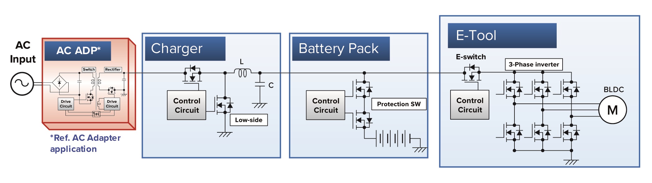 Figure 1: Most cordless power tools have a similar fundamental layout
All cordless power tools need to be recharged, usually from AC mains power. Generally, the battery pack is removed from the tool and plugged into a charger. This allows the user to work continuously, as long as they have multiple batteries.
The charger front-end is an AC adapter, used to rectify and condition the AC input and provide power to a circuit that charges the battery. As the type and size of battery is known, the charger can be optimised for size and efficiency requirements. Battery packs now hold significant amounts of energy. Increasing sophistication means they often contain control and protection circuitry, ensuring safe and consistent delivery of power to the tool.
The tool itself contains the motor drive circuitry, which comprises a control circuit and three-phase inverter built from discrete semiconductors that create the interleaved power signals to correctly drive the BLDC motor.
Challenges for designers
With cordless power tools, many challenges interact and, in some cases, compete with each other.
The ergonomics that define the form factor is one challenge. Comfort and convenience are essential, as these tools are often used all day. The shape of the tool defines the tactile user interface but also defines the space for the motor and electronics.
Weight is another key criterion, defining the motor choice; a BLDC is the lightest DC motor. Weight also dictates the battery and housing choices. The battery is one of the biggest trade-offs, as users demand lighter tools with extended operating times, while also expecting power-consuming features such as integrated LED lights. This means that designers are faced with finding the 'sweet spot' between weight and operating time. To maximise life between charges, designers must ensure efficiency in all aspects of the design.
Even in normal use, tools will experience mechanical and electrical stresses and peaks. Control and protection circuitry is needed to ensure that excess battery cannot damage the electronics or motor. Dust, dirt and damp are common environmental hazards that require tools to be physically sealed. Temperature is another issue, although improved efficiency allows tools to work at higher temperatures.
Finally, failed tools will damage the manufacturer's reputation. This means that ensuring reliability and robustness are high on the agenda of all cordless power tool designers.
Optimising efficiency
Ensuring that cordless power tools operate at the highest efficiency makes best use of the available battery energy. Switching MOSFETs have the largest impact,as they can be found throughout the tool (illustrated in each of the building blocks shown in Figure 1). By using an efficient topology, and selecting the optimum MOSFETs, designers can deliver significant competitive advantage.
Batteries continue their significant technology advances. In general, voltages are increasing, with 12 and 14.4V versions being replaced by batteries in the 18 to 21V category. More recently, there has been a growth in 36V options. These higher voltages deliver more power rapidly and are required for larger tools. Most tools incorporate Li-Ion technology. These batteries exhibit no memory effect and typically weigh 40% less than the equivalent nickel–metal hydride (NiMH) battery. The result is a weight advantage and the ability to support 'top-up' charging.
Advanced MOSFET technologies
One of the more recent technologies specifically aimed at meeting the challenges of cordless power tool design are U-MOS ‘Trench’ LV MOSFETs from Toshiba Electronics Europe (TEE). The company’s U-MOS VIII MOSFET technology, for example, offers a broad product range of 30 to 250V class MOSFETs. The latest U-MOS IX-H technology supports 30 to 60V class MOSFETs with RDS(ON)max values as low as 2.3mΩ in a 3.0 x 3.0mm 40V package. For devices in a 5.0 x 6.0mm 40V package, this value drops further to 0.85mΩ.
In developing U-MOS technology, TEE focused on three main parameters affecting power switching losses, namely gate charge (Qg), on-resistance (RDS(ON)) and recovery charge (Qrr or Qoss/Eoss). The gate charge and recovery charge have the greatest impact in high-speed applications, while high values of RDS(ON) generate waste heat when the MOSFET is conducting current.
The U-MOS range offers several performance levels and combinations of these critical parameters, allowing designers to select the most appropriate for a particular application. The company plans to broaden the range further with the introduction of 100 and 80V devices in the future.
The relationship between Qg and RDS(ON) is important, as there is a trade-off between the two parameters. This means that an improvement in static losses can negatively impact dynamic losses, and vice-versa. However, this trade-off has improved with each generation. The latest U-MOS IX-H (U-MOS 9) shows a 26% improvement in RDS(ON) versus Qg over U-MOS VII (U-MOS 7) and reduces recovery loss by tuning Qoss. As the ever-important RDS(ON) is driven lower, so conduction losses are reduced. In a 5.0 x 6.0mm package, U-MOS IX-H delivers what Toshiba believes is a market-leading value of 0.36mΩ at 30V and 0.65mΩ at 40V.
When developing cordless power tools, a wide choice of package types and cooling methods is important. (For example, Toshiba offers various choices in its LV-MOSFET range.) Additional cooling features allow heat to be quickly and easily channelled in thermally advanced packages, such as Toshiba’s TSON Advance and SOP Advance packages, which feature underside cooling, while its dual-side DSOP Advance offers additional topside cooling. In the case of the DSOP option, a direct connection between the die, the PCB and heatsink delivers a significant increase in thermal conductivity. Devices in this package type are particularly well suited to cordless power tool applications, where opportunities for convection cooling are often limited.
The DSOP package competes with conventional, and relatively expensive, metal can packages. These require solder joint control by x-ray, whilst with a DSOP package a portion of the PIN is exposed.
Compared with other plastic mould packages with dual sided cooling that are on the market, the Toshiba DSOP has the advantage of a wider top side connector. This ultimately leads to improved Rth to the topside. Therefore it is a simple step for customers to upgrade from the existing concept of 5.0 x 6.0mm standard items with advanced DSOP versions.
Each of the building blocks of a cordless power tool will benefit from improvements in MOSFET technology. Within the charger, MOSFETs are key switching elements, while in the battery pack, MOSFETs provide protection in fault conditions. In the tool itself, MOSFETs are used for the e-switch as well as for providing the motor drive. Examples of MOSFET options for each block are illustrated in Figure 2.
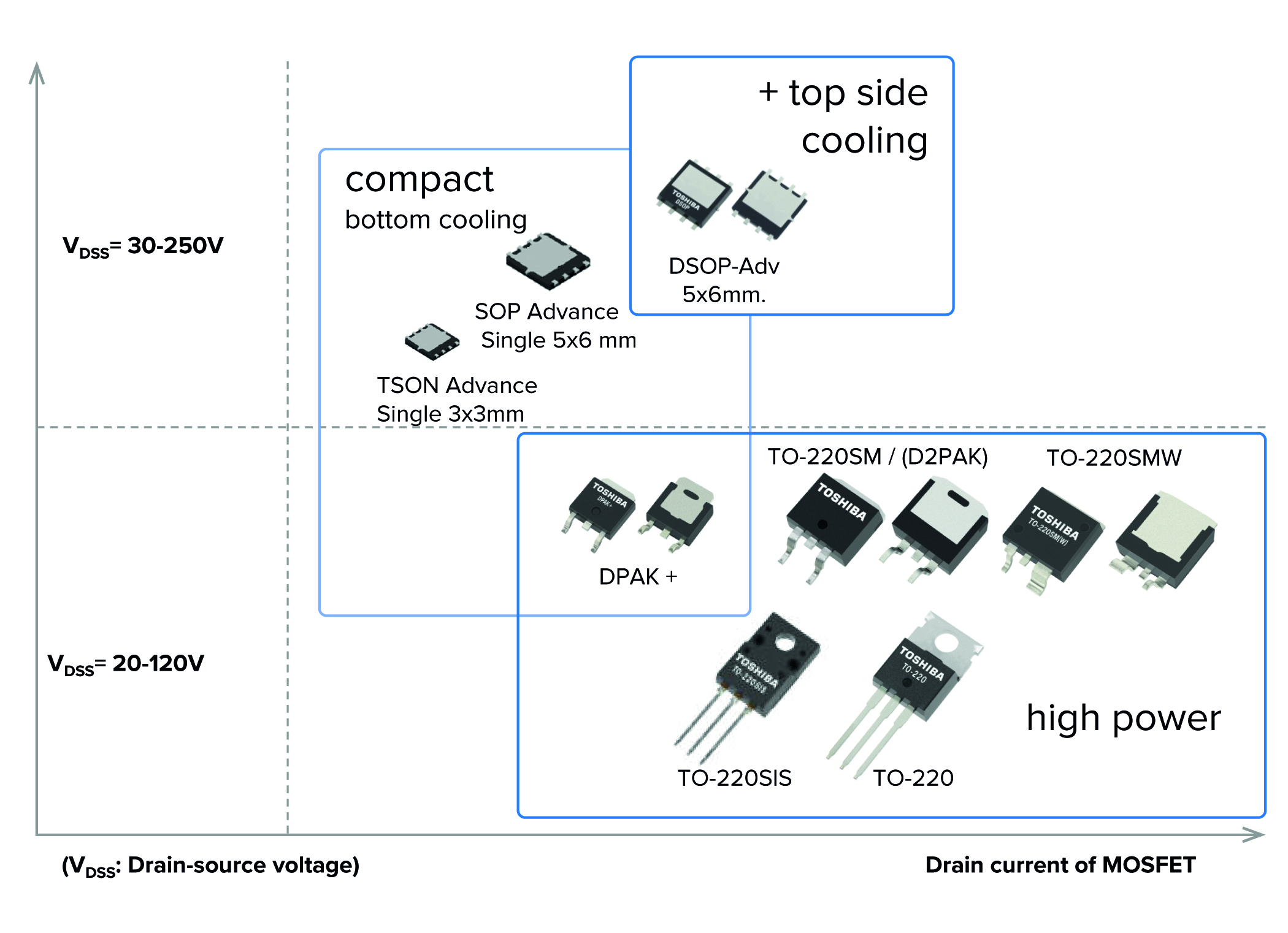
Figure 2: Package types offered by Toshiba in its LV-MOSFET range
Figure 2 shows the options for different battery voltages afforded by the U-MOS LV-MOSFET range. As can be seen, a tool with four or five battery cells, powering a BLDC motor can use the devices shown in blue for the ultimate performance for high-end tools. The devices shown in black are those that offer the best price/performance trade-off, and are targeted at cordless tools aimed at the DIY market.
Toshiba at PCIM Europe 2017: Stand 9-301
Product Spotlight
APV1111GVY
Panasonic

Panasonic PhotoMOS® Photovoltaic MOSFET High-Power Drivers
| SKU: | |
|---|---|
| Stock: | 3490 |
| Cost: | $3.95 |
