
Point & Click for embedded developers
How a comprehensive approach to software platforms can provide rapid prototyping and development of ARM Cortex-M based applications. By Harrold Spier, Senior Software Engineer & Ulrich Kloidt, Senior Support Engineer, Altium Europe.
Embedded software development is a complex and time consuming process, with a wide variety of MCU architectures available on the market and many different ways to configure the on-chip peripherals of those architectures. As embedded devices have limited memory, CPU speed and power, developers must observe these limitations, particularly as the complexity of applications rises. This is illustrated by the trend for networked devices. As a result, product development engineers need to be able to focus on coding the embedded application itself rather than writing peripheral drivers from scratch.
Altium developed the TASKING Software Platform to deliver rapid prototyping and development of MCU applications. Using this tool to bring the middleware framework and the low-level peripheral drivers together means building an application can take just a few mouse clicks within the Eclipse based IDE.
The idea for the Software Platform came in late 2012 when developers asked us why developing embedded software takes so much more time than developing a similar desktop application. This seems a legitimate question; simply displaying ‘Hello World!’ on the LCD of an embedded evaluation board requires a surprisingly large amount of effort. From driving the LCD and converting characters to pixels, to keeping track of the cursor, nothing seems to work automatically. And even if convenient libraries are available, for example for TCP/IP communication, then there is still a lot of work to be done to make the new code fit into the application and to configure it correctly. This cycle often repeats itself for every new project.
Searching for a better solution
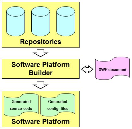
This challenge motivated Altium to come up with what is now called the Software Platform. The basic concept is quite simple; put generic software components in a repository and provide them with a uniform interface, and ensure the software components can be configured in a standardised manner. This way, one does not have to know how each component is built up internally; the unified interface means components can easily work together.
A graphical environment presents the software components as coloured blocks, where required blocks are picked from the repository to create a starting point for the application. Components can be configured to match the application's requirements, while relationships between selected components can be specified.
The Software Platform is all about integration of content. It is not the content itself that makes it so special. Much of the current content comes from third parties and can be downloaded freely from the Internet. However, creating an application with a bunch of collected software components is not so easy, that is where the Software Platform is helpful. It provides the content in a way that ensures everything works smoothly together. All components can be configured in a similar way and that combination creates the possibility to build reliable applications rapidly.
The Software Platform Builder can be used for the creation of ARM Cortex-M CPU based applications. The Software Platform itself includes various software modules which are added to the application code if needed, like RTOS facilities, peripheral access or software protocols. The Software Platform is both a graphical editor and a code generator. Collections of software modules are delivered as Software Platform repositories.
The repository may contain any kind of software, but typical modules include interrupt services, timers, peripherals (hardware wrappers), drivers, kernel services (such as POSIX multithreading), device I/O, file system (FatFs), networking (TCP/IP), graphical user interface and more. The TASKING ARM Cortex tools include a large number of Software Platform reference projects for various STM32 evaluation boards utilising the available peripherals of the different boards.
Structure of the repository
Software Platform repositories can contain numerous software modules that take care of lower level software routines as well as modules that offer extra functionality by providing the user with a convenient API. The Software Platform consists of device stacks and software services.
Device stacks are all about making hardware peripherals available to application code through abstract and generic software interfaces. By placing more or fewer modules on a stack, the abstraction level which should be used in the application is specified. The lowest level modules are specific for a particular hardware device, but on top of that higher level modules can be added which provide more generic functionality to access the device. For example, at the higher abstract level, a module to access a file system in the application can be selected. At the lower levels it is still possible to select modules to decide which specific storage device is accessed (a hard drive, SD card, RAM drive, etc.). Thus, the lower level modules are more specific for a particular peripheral while the higher level modules are less hardware specific and can even be used in combination with multiple peripheral devices.
Peripherals (the green stack items) are the lowest level modules. They provide information for the higher layers of the stack to access the peripherals. Information such as the base address and interrupt assignment is stored in the peripherals. In most situations, an application does not access the peripherals directly, because the application accesses them through the driver's interface on top of it.
Drivers (the yellow stack items) provide the next level of abstraction. They provide low-level access to specific hardware either via a peripheral or via another driver. The difference between a driver and a peripheral is well defined; the peripheral only defines basic information about the hardware but provides no further functionality. This basic information can be used by a driver which is placed on top of the peripheral. Drivers are hardware specific and so are the interfaces they offer. Hence, if the application contains code that accesses a driver's API, it will be hardware dependent. Drivers still operate at a low abstraction level and using a device at the driver level requires knowledge of that particular driver's interface.
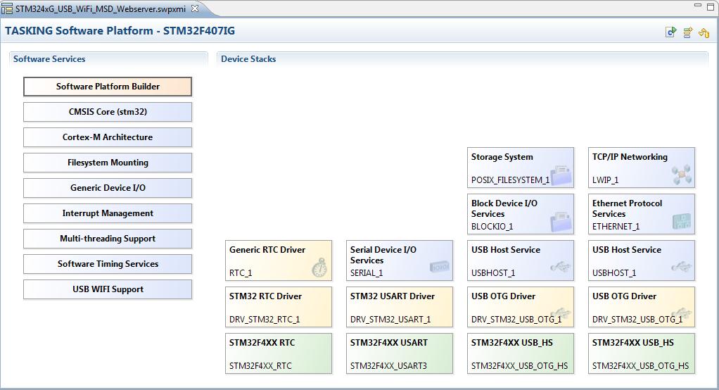
Figure 2 - Device Stacks and Software Services
Some drivers are available as library wrappers. They only offer an initialisation routine which is called from an application in order to configure pins, clocks and registers. After this initialisation the peripheral driver libraries from silicon vendors can be used.
Stack services (the blue stack items) are the most abstract layers of functionality. Stack services provide standardised, hardware independent access to devices. Stack services ensure the portability of an application. For example, if the application uses a generic TCP/IP service, it remains the same if Ethernet is replaced with PPP and serial. A portable TCP/IP application works exactly the same, whether linked to a UART or to an EMAC peripheral, since the Software Platform handles the lower level details.
Software services
Some services are static and not meant to be instantiated. They have no (direct) relationship with peripherals or other services and facilitate common functionality like POSIX multithreading, CMSIS, software timer or interrupt management support. The software services may also be added automatically if they are required by other services.
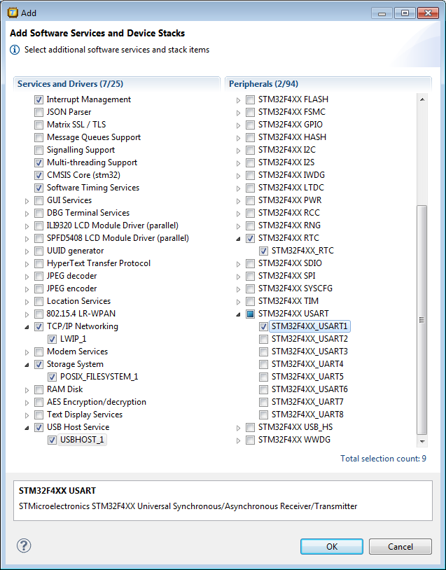
Figure 3 - Adding Software Services and Device Stacks
It takes just a few steps to integrate the Software Platform into an Eclipse based TASKING ARM Cortex tools project. First the Software Platform document needs to be added to the project. The required Software Services and Device Stacks are appended using the 'Add' menu by enabling the related check box (Figure 3). After a Device Stack has been selected in the Software Platform document the available stacks for the device can be chosen using the Grow stack up or Grow stack down option. Figure 4 shows the stack items for the USB On-The-Go Full Speed interface. Device stacks can be configured by changing the options in the Properties view. Figure 5, for example, shows the configuration options of the Stack Service for the USB Host.
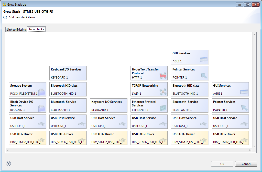
Figure 4 - Stack Items for USB_OTG_FS
After the Software Platform is configured, all C files and header files which belong to the devices used are added (copied) to the Eclipse project. If device parameters are changed, the project files can be updated by selecting the 'Generate Code' button. From within the source code of the embedded project the Software Platform functions are called like other C functions. The assignment of the functions, their parameters and also data structures used (if applicable) are described in an online API help.
The use of software modules in the Software Platform offers various benefits. Some important ones are that software modules are integrated; they relate and interact with other modules. This increases the quality of the modules because they are used in different contexts and they can be reused. All information of a component is encapsulated in a consistent manner which allows higher abstraction layers, allowing it to be used to customise or configure the embedded system with less user intervention. Because the low level drivers are part of the software repository, the embedded software developer does not need to interfere with those parts which require a thorough knowledge of how the peripheral works, and can instead concentrate on the application development itself.
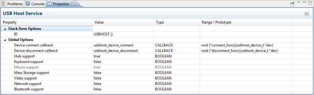
Figure 5 - USB Host Service
Since the Software Platform Builder creates the code to configure the software repository modules during compile time, this allows a precise configuration and prevents unnecessary functionality from being linked, with the goal of reducing memory usage. Last but not least the Software Platform can be expanded providing the possibility to adapt existing modules or to create and add new modules to extend its functionality.
Product Spotlight
APV1111GVY
Panasonic

Panasonic PhotoMOS® Photovoltaic MOSFET High-Power Drivers
| SKU: | |
|---|---|
| Stock: | 3490 |
| Cost: | $3.95 |
